Spanning device for erecting cables across ditches

A technology for erecting cables and ravines, which is applied in the field of line erection equipment, can solve problems such as inability to cross ravines, and achieve the effect of ensuring stability and increasing counterweight

Inactive Publication Date: 2019-07-09
国网内蒙古东部电力有限公司建设分公司 +1
View PDF10 Cites 0 Cited by
  • Summary
  • Abstract
  • Description
  • Claims
  • Application Information

AI Technical Summary

Problems solved by technology

In the above scheme, the anti-running rods arranged at both ends of the rotating rod wrap around the rotating rod to form an accommodating space for the electric wires; the top of the telescopic rod can be raised to raise the electric wires, thereby crossing other The obstacle formed by the cable is used for stringing operations; but it cannot realize the crossing of the gully, so it cannot form a stable support on one side of the gully, and realize that one side can directly cross to the opposite bank for work

Method used


Image

  • Spanning device for erecting cables across ditches
  • Spanning device for erecting cables across ditches
  • Spanning device for erecting cables across ditches

Examples


Embodiment 1

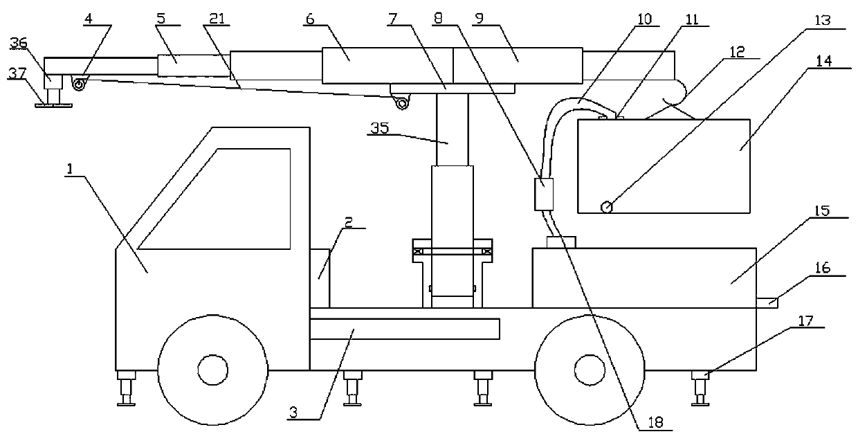
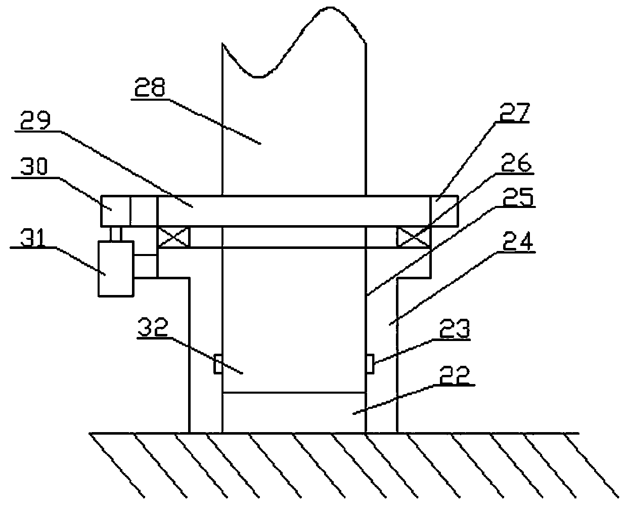
[0026] Such as Figure 1-4 Shown: a spanning device for erecting cables across ravines, including a carrier vehicle 1, a supporting mechanism arranged at the lower part of the carrier vehicle 1, a rotating mechanism arranged on the carrier vehicle, and a telescopic telescopic mechanism arranged on the rotating mechanism mechanism, a spanning mechanism arranged at the upper end of the telescopic mechanism, a counterweight mechanism disposed at one end of the spanning mechanism, and a counterweight mechanism disposed on the carrier vehicle for controlling the supporting mechanism, the rotating mechanism, the telescoping mechanism, the spanning mechanism and the counterweight The control mechanism of the heavy mechanism;

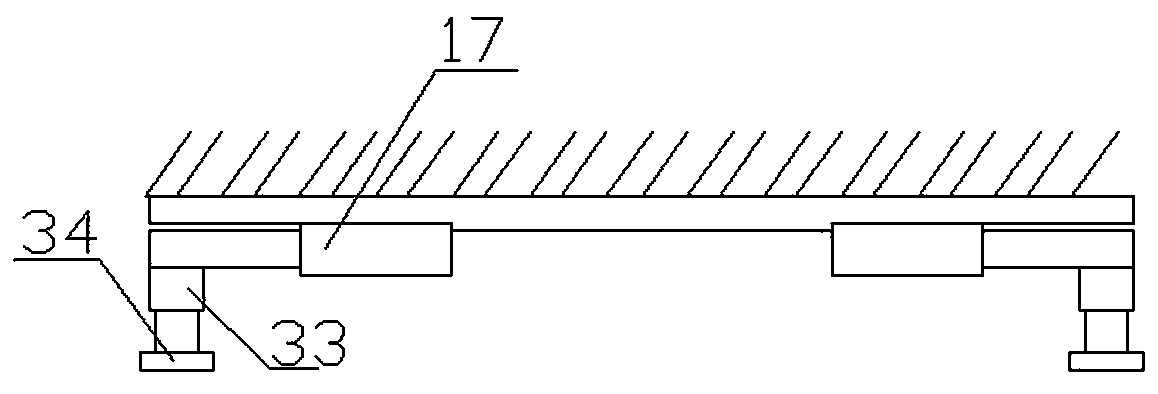
[0027] Described support mechanism comprises a plurality of lateral telescopic arms 17 arranged on the peripheral side of the vehicle, a vertical telescopic arm 33 arranged at the end of the lateral telescopic arm 17, and a support provided at the lower end of ...

Embodiment 2

[0035] Such as Figure 4 Shown, its difference with embodiment one is:

[0036] An electric hoist is arranged on the hanging hook, and the lower end of the electric hoist is connected with a counterweight water tank.

[0037] In this embodiment, the electric hoist can be used to lift the heavy counterweight water tank to a certain height to ensure that it can be loaded on a car or close to the ground. Of course, a manual hoist can also be used for lifting.

Embodiment 3

[0039] Such as Figure 5 Shown, its difference with embodiment two is:

[0040] A MEMS gyroscope 19 and a MEMS accelerometer 20 are arranged at the center of the vehicle.

[0041] The MEMS gyroscope and MEMS accelerometer adopted in this embodiment can detect the change of the center of gravity, so that the operator can be prompted by the computer to deal with it in time, such as extending the telescopic arm of the counterweight, or adding more counterweights to the counterweight water tank. heavy water.


PUM


Abstract

The invention provides a spanning device for erecting cables across ditches, which comprises a carrier vehicle, a supporting mechanism arranged at the lower part of the carrier vehicle, a rotating mechanism arranged on the carrier vehicle, a telescopic mechanism arranged on the rotating mechanism, a spanning mechanism arranged at the upper end of the telescopic mechanism, a counterweight mechanismarranged at one end of the spanning mechanism, and a control mechanism arranged on the carrier vehicle to control the supporting mechanism, the rotating mechanism, the telescopic mechanism, the spanning mechanism and the counterweight mechanism. In view of the difficulty in crossing ditches in the prior art, the device is arranged on one side of a ditch, a spanning structure is directly formed above the ditch by erection, a stable conveying structure is formed through the cooperation of the mechanisms of the device, and the spanning device is quickly recovered through the control mechanism after erection. Thus, erection across ditches is very simple and convenient, and the spanning device can be quickly recovered after use.

Description

technical field [0001] The invention relates to the technical field of line erection equipment, in particular to a spanning device for erecting cables across ravines. Background technique [0002] In the process of line erection, the erection route will be designed according to the needs of the terrain. When encountering a ravine, it is often used to go down to the bottom of the valley and then climb to the opposite side, and then use the pulling rope and steel braze that were carried before to build a temporary transportation frame, in order to realize the erection across the ravine, but this erection method is often due to the limitation of existing equipment, which often results in a long construction period and great difficulty in erection. Set up the spanning structure, so as to realize the need of laying cables across the ravine. [0003] In the authorized announcement number CN205753199U, a cross-river stringing construction device is disclosed. The frame is erected...

Claims


Application Information

Patent Timeline
Patent Type & Authority Applications(China)
IPC IPC(8): H02G1/04
CPCH02G1/04
Inventor 田秋松
Owner 国网内蒙古东部电力有限公司建设分公司
Why Eureka
Try Eureka