Motor and suction blower

A technology of motors and brushes, which is applied in the direction of electrical components, electromechanical devices, etc., can solve the problems of large limitations and mechanical structures added to the motor, and achieve the effects of prolonging the life of the motor, suppressing electric sparks, and better versatility

Pending Publication Date: 2019-07-09
POSITEC POWER TOOLS (SUZHOU) CO LTD
View PDF0 Cites 0 Cited by
  • Summary
  • Abstract
  • Description
  • Claims
  • Application Information

AI Technical Summary

Problems solved by technology

But this will cause the motor to add a more complex mechanical structure, so the limitation is greater

Method used


Image

  • Motor and suction blower
  • Motor and suction blower
  • Motor and suction blower

Examples


Embodiment Construction

[0022] In order to make the object, technical solution and advantages of the present invention clearer, the present invention will be further described in detail below in conjunction with the accompanying drawings and embodiments. It should be understood that the specific embodiments described here are only used to explain the present invention, not to limit the present invention.

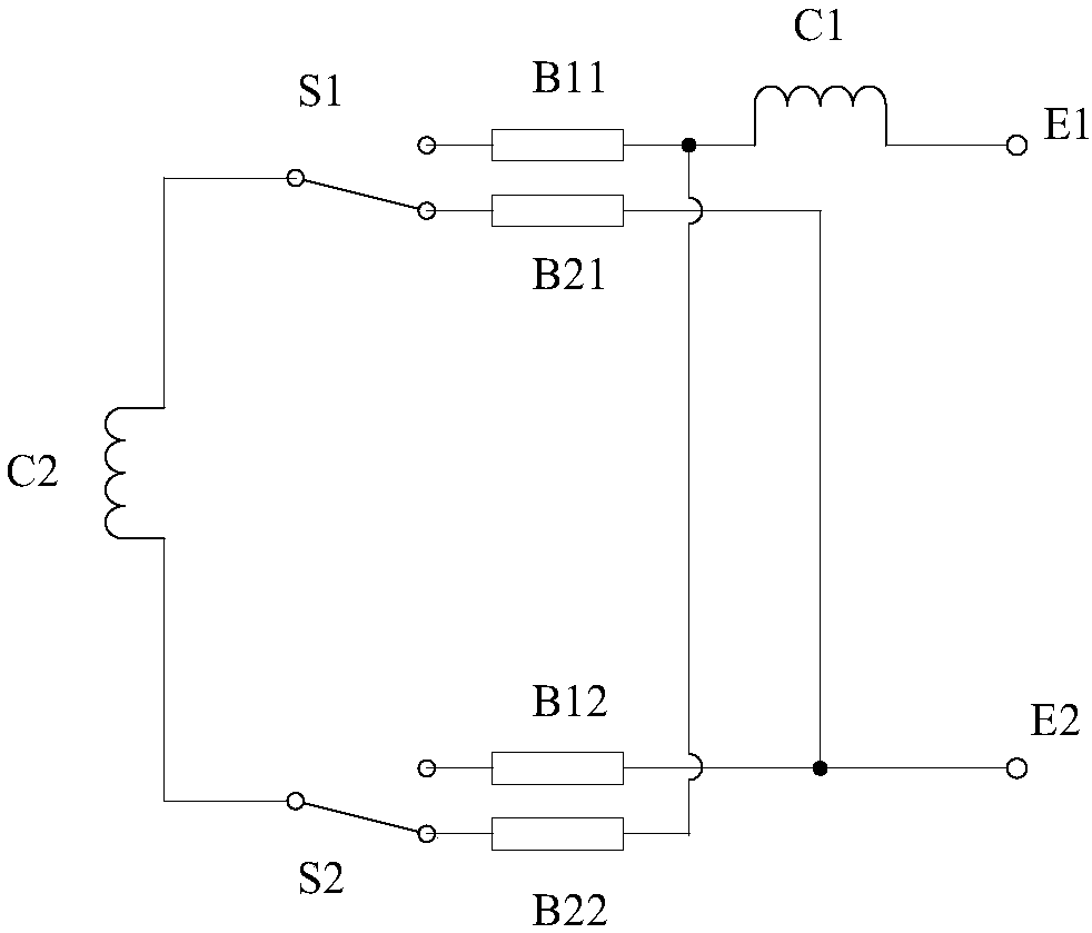
[0023] In one embodiment, the motor of the present invention includes a motor circuit, a commutator, a first brush group, a second brush group and a switch unit, and each of the first brush group and the second brush group includes two brushes . The switch unit is used to connect the first brush group to the motor circuit and disconnect the second brush group from the motor circuit when the motor is rotating forward, and is also used to connect the second brush group to the motor circuit when the motor is reverse motor circuit, and disconnect the first brush set from the motor circuit. The includ...


PUM


Abstract

The invention relates to a motor and a suction blower. The motor comprises a motor circuit and a commutator and also comprises a first brush set, a second brush set and a switch unit, wherein each ofthe first brush set and the second brush set comprises two brushes, and the switch unit is used for connecting the first brush set into the motor circuit and disconnecting the second brush set from the motor circuit when the motor rotates forwards and is also used for connecting the second brush set into the motor circuit and disconnecting the first brush set from the motor circuit when the motorrotates reversely; and the included angle between the first brush set and the commutator is a first borrowed drift angle, and the included angle between the second brush set and the commutator is a second borrowed drift angle. According to the motor, one brush set is used during forward rotation of the motor and the other brush set is used during reverse rotation of the motor, it is guaranteed that the borrowed drift angles of the brushes can be maintained at preset ideal angles regardless of forward rotation and reverse rotation of the motor, electric sparks generated during forward/reverse rotation of the motor are suppressed, and the life of the motor is prolonged.

Description

technical field [0001] The invention relates to a motor, in particular to a brush of the motor, and also to a motor of a blower. Background technique [0002] There is mechanical wear between the brush and the commutator of the motor. If it is used improperly, it will produce serious sparks and affect the life of the motor. see figure 2 , when the armature winding is energized, a magnetic field will be generated around the armature 10. After the combination of this magnetic field and the main magnetic field, the main magnetic field will be distorted relative to that before the synthesis, so that the geometric neutral line 11 of the main magnetic field will be generated relative to the physical neutral line 13 offset. Therefore, in order to suppress the electric spark, it is necessary to suppress the reactance potential generated during the commutation process. For example, the brush can be set to form an angle with the physical neutral line of the commutator. This angle is...

Claims


Application Information

Patent Timeline
Patent Type & Authority Applications(China)
IPC IPC(8): H02K13/14
CPCH02K13/14
Inventor 何明明查霞红卢惠李先峰
Owner POSITEC POWER TOOLS (SUZHOU) CO LTD
Why Eureka
Try Eureka