

Wave-guide cavity in use for microwave sulfur lamp
A waveguide cavity and sulfur lamp technology, applied in the field of waveguide cavity, can solve the problems of time-consuming and labor-intensive, and achieve the effect of suppressing the spark phenomenon
Inactive Publication Date: 2007-12-26
LG ELECTRONICS (TIANJIN) APPLIANCES CO LTD
View PDF0 Cites 0 Cited by
- Summary
- Abstract
- Description
- Claims
- Application Information
AI Technical Summary
Problems solved by technology
Obviously, this method is time-consuming and labor-intensive, and it is inevitable that there will be some omissions, so it is not an ideal solution
Method used
View moreImage
Smart ImageViewing Examples

Examples
Embodiment Construction
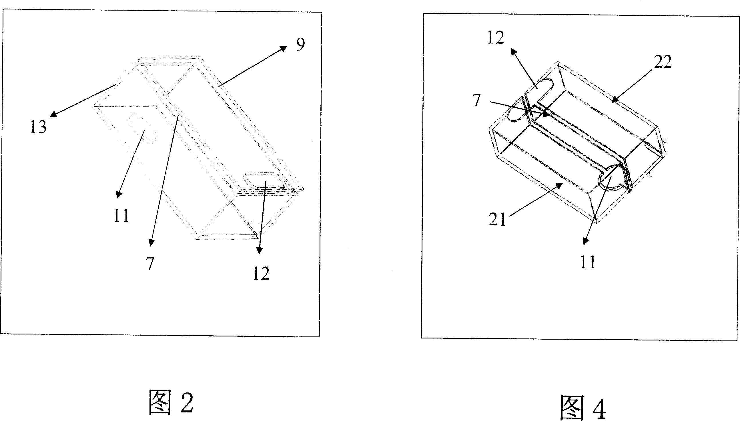
[0015] Referring to Fig. 4, the waveguide cavity is formed by docking the front cavity 22 and the rear cavity 21. The front cavity 22 and the rear cavity 21 are made of metal aluminum die-casting, and the magnetron input hole 11 and the radiation hole 12 are connected together. And molded by die casting, the butt joint of the front cavity body 22 and the rear cavity body 21 is located at the centerline of the waveguide cavity, and finally they are connected into one body with bolts (not shown).
Login to View More PUM
 Abstract
Wave-guide cavity in use for microwave sulfur lamp is composed of front cavity and back cavity butt jointed each other. There is an input hole of magnetron on left side at base, and there is an irradiation hole on right side at top. Since fabricated slot is located at midline of the wave-guide cavity, when surface current generated by electromagnetic wave runs inside, the disclosed wave-guide cavity does not generate phenomena of striking fire at the fabricated slot so as to raise safety as well as reduce wastage of energy.
Description
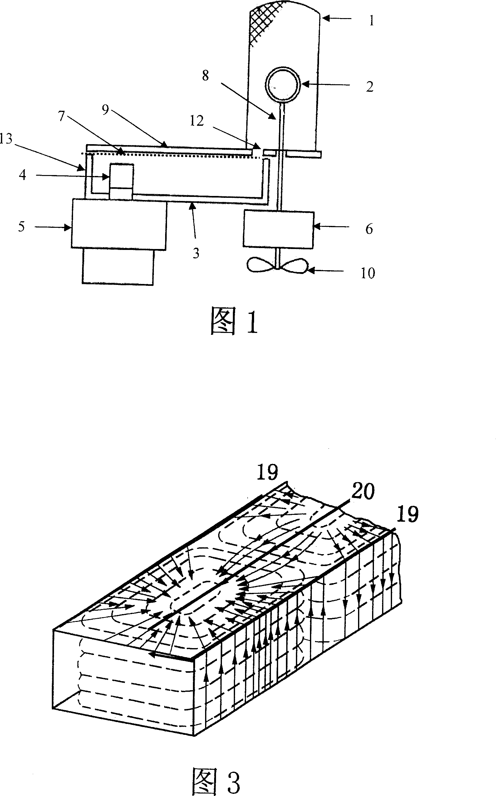
1. Technical field [0001] The invention relates to a waveguide cavity for a microwave sulfur lamp, in particular to a waveguide cavity for a microwave sulfur lamp which is not easy to spark from a gap. 2. Technical Background [0002] Microwave sulfur lamp is a new type of light source that uses a new light-emitting mechanism to emit light. It has the advantages of energy saving, long service life, good light color and less pollution. Its light emitting process is as follows. [0003] Refer to Figure 1 and Figure 2. The sulfur lamp bulb 2 is placed in the resonant cavity 1, and is rotated by the motor 6 through the lamp handle 8, and the fan 10 plays a cooling role; the waveguide cavity 3 is formed by connecting the lower cavity 13 and the upper cover 9; the magnetron 5 The output part 4 is inserted into the waveguide cavity 3 through the magnetron input hole 11 on the left side of the lower cavity 13, and the electromagnetic wave emitted by it is radiated to the sulfur la...
Claims
Login to View More Application Information
Patent Timeline
 Patent Type & AuthorityApplications(China)
IPC IPC(8): H01J65/04
Inventor任建伟
OwnerLG ELECTRONICS (TIANJIN) APPLIANCES CO LTD