Method and tool device for testing equipment communication port

A communication port and test equipment technology, applied in the field of optical communication, can solve the problem of high cost

Active Publication Date: 2019-07-09
ZTE CORP
View PDF6 Cites 3 Cited by
  • Summary
  • Abstract
  • Description
  • Claims
  • Application Information

AI Technical Summary

Problems solved by technology

[0004] In related technologies, QSFP or QSFP+ optical modules are used to test the QSFP+ port of the device, but because the optical module needs to perform optical signal processing (including high-speed photoelectric conversion and electro-optical conversion modules and high-speed signal processing parts), the cost is relatively high

Method used


Image

  • Method and tool device for testing equipment communication port
  • Method and tool device for testing equipment communication port
  • Method and tool device for testing equipment communication port

Examples


Embodiment 1

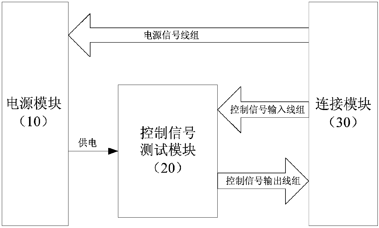
[0023] Such as figure 2 As mentioned above, the embodiment of the present invention provides a tooling device for testing the communication port of equipment, including: a power supply module 10 , a control signal testing module 20 and a connection module 30 ;

[0024] The power supply module is configured to receive a power supply signal from a set of power signal lines and use the power supply signal to at least supply power to the control signal test module;

[0025] The control signal testing module is configured to perform logical processing on the control signal after receiving the control signal output by the device, and return the control signal after the logical processing to the device;

[0026] The connection module is used to pluggably couple the tooling device and the equipment communication port;

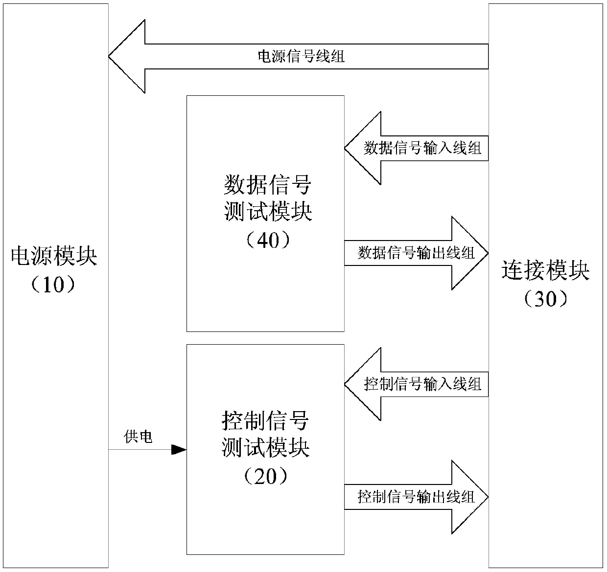
[0027] In one embodiment, as image 3 As shown, the tooling device also includes a data signal testing module 40;

[0028] The data signal test module is used to r...

Embodiment 2

[0047] Such as Figure 5 As shown, the embodiment of the present invention provides a method for testing a communication port of a device, which is applied to a device with the communication port, including:

[0048] Step S510, sending a control signal to the tooling device through a control signal output line, and receiving a control signal returned by the tooling device from a corresponding control signal input line;

[0049] Step S520, judging whether the received control signal and the sent control signal satisfy a predetermined logical relationship, and determining whether the control link of the communication port is normal according to the judging result.

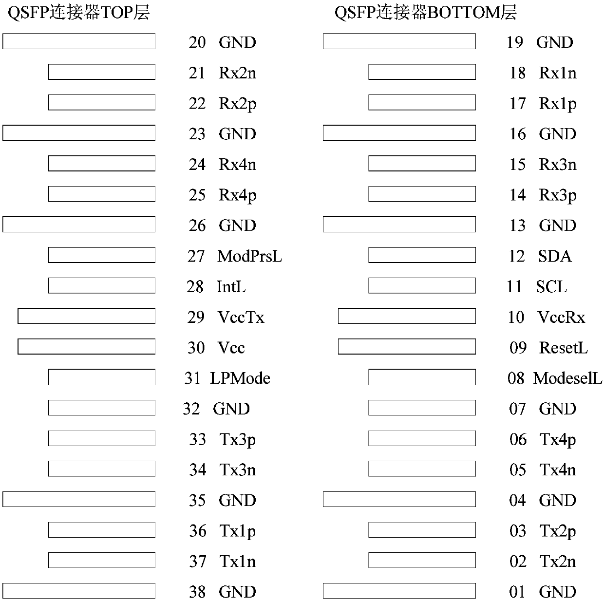
[0050] In one embodiment, the communication port is a four-channel small form factor pluggable port QSFP or QSFP+;

[0051] Based on the signal direction of the device, the four-channel small package pluggable port QSFP or QSFP+ at least includes: multiple data signal input lines, multiple data signal output lines, ...

example 1

[0071] Such as Image 6 As shown, in this example, the device includes a four-channel small package pluggable port, and the four-channel small package pluggable port is coupled to the test fixture device through a gold finger connector (referred to as gold finger).

[0072] Such as Image 6 As shown, the test tooling device includes: a data signal test module A, a control signal test module B, a power signal test and power supply module C and a golden finger D. Wherein, the data signal testing module A includes a repeater A1. The control signal test module B includes two selectors B1, B2 and EEPROM memory B3. The power signal test and power supply module C includes a power module C1 and an LED (Light Emitting Diode, light emitting diode) indicator light C2.

[0073] After the tooling device is inserted into the device port, if the device works normally (not in the test state), the device port outputs a reset signal ResetL (the reset signal is active at low level) as a high ...


PUM


Abstract

The invention discloses a method and a tool device for testing an equipment communication port. The tool device for testing the communication port of the equipment comprises a power supply module, a control signal testing module and a connecting module, the power supply module is used for receiving a power supply signal from a group of power supply signal lines and at least supplying power to thecontrol signal testing module by utilizing the power supply signal; the control signal testing module is used for receiving the control signal output by the equipment, performing logic processing on the control signal, and returning the control signal subjected to the logic processing to the equipment; the connection module is used for being coupled with the tool device and the equipment communication port in a pluggable mode. According to the technical scheme, the signal test of the pluggable communication port can be realized, the cost is low, and the test flexibility is high.

Description

technical field [0001] The invention relates to the technical field of optical communication, in particular to a method and a tooling device for testing a communication port of equipment. Background technique [0002] With the continuous development of optical communication technology, the optical transmission rate continues to increase. Communication equipment (hereinafter referred to as equipment) using 40G (transmission rate of 40Gbps) ports and supporting 40G optical modules are widely used in optical communication systems. QSFP (Quad Small Form-factor Pluggable, four-channel small form-factor pluggable) or QSFP+ optical module occupies an important position in the 40G transmission field due to its advantages of simple structure, high port and wiring density, and low cost. As a device using QSFP or QSFP+ ports, the port test has become a very important and indispensable work. [0003] figure 1 It shows the interface line of a QSFP or QSFP+ port of a device and the posi...

Claims


Application Information

Patent Timeline
Patent Type & Authority Applications(China)
IPC IPC(8): H04B10/073
CPCH04B10/073
Inventor 赵丽爽
Owner ZTE CORP
Why Eureka
Try Eureka