Rotor, electric machine containing such rotor and method for making rotor

A technology of rotor and rotor shaft, which is applied in the direction of engine control, manufacturing of motor generators, mechanical equipment, etc., can solve problems such as broken metal wires of armature windings, and achieve the effect of reducing load

Active Publication Date: 2021-10-08
ROBERT BOSCH GMBH
View PDF8 Cites 0 Cited by
  • Summary
  • Abstract
  • Description
  • Claims
  • Application Information

AI Technical Summary

Problems solved by technology

There is thus the risk of the wires of the armature winding breaking under severe external vibration loads

Method used


Image

  • Rotor, electric machine containing such rotor and method for making rotor
  • Rotor, electric machine containing such rotor and method for making rotor
  • Rotor, electric machine containing such rotor and method for making rotor

Examples


Embodiment Construction

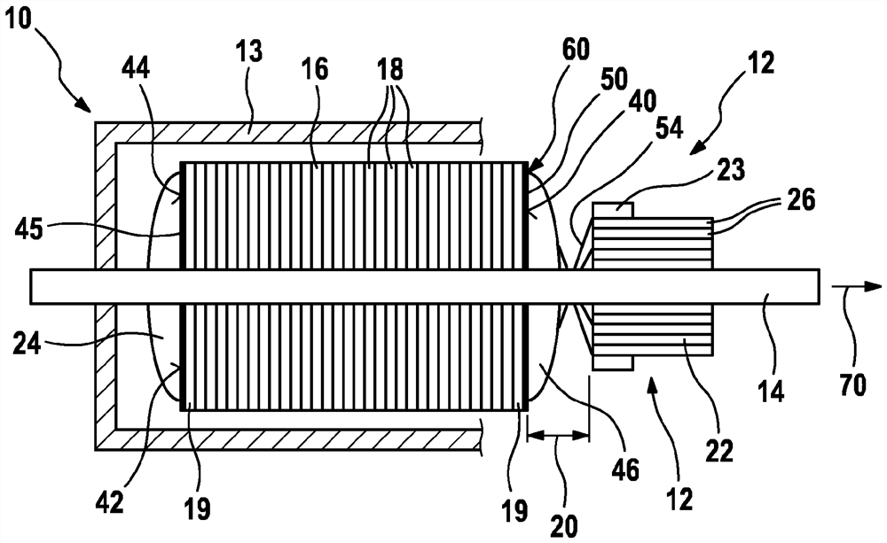
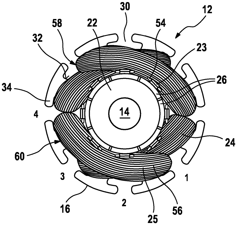
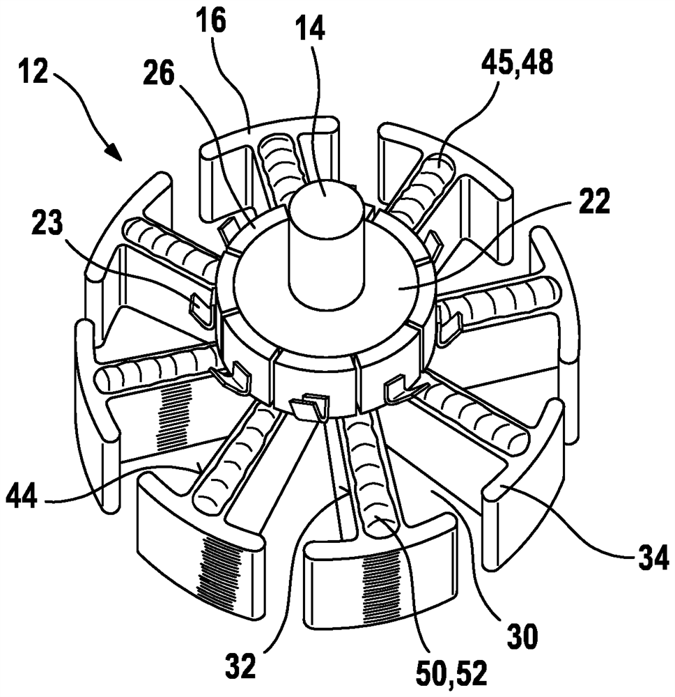
[0024] figure 1An electric machine 10 is shown schematically in FIG. 1 , wherein a rotor 12 is mounted in a stator 13 . The rotor 12 has a rotor shaft 14 , on which a rotor lamination stack 16 is fastened, which consists of individual magnetic steel lamination cores 18 , wherein the corresponding end laminations 19 First and second end faces 40 , 42 of the rotor lamination stack 16 are formed. The magnetic steel laminated core 18 is usually stamped from electrical steel sheets. The rotor core 16 is, for example, pressed against the rotor shaft 14 and fixed thereon in a rotationally fixed manner. A commutator 22 is attached to the rotor shaft 14 around an axial region 20 spaced apart from the rotor lamination core 16 . The commutator is likewise pressed against the rotor shaft 14 , for example in a rotationally fixed manner. An electrical winding 24 , which is electrically connected to a rectifier 22 , is arranged on the rotor core 16 . To this end, the rectifier 22 has re...


PUM


Abstract

The invention relates to a rotor and an electric machine (10), in particular for motorized adjustment of movable parts in a motor vehicle, and to a method for producing such a rotor with a rotor shaft (14 ), on which is fixed a rotor lamination stack (16) and a commutator axially spaced from the rotor lamination stack for receiving a rotor winding (24), wherein the rotor winding (24 ) on selected limited areas of the rotor lamination stack (16) are directly glued to the rotor lamination stack (16) by means of an adhesive (50).

Description

technical field [0001] The invention relates to a rotor of the type described in the independent claims, an electrical machine comprising the rotor and a method for producing the rotor. Background technique [0002] A direct current motor is known from EP 0 895 668 B1, in which the lamination pack is fixed on the armature shaft. After the laminations have been installed, these laminations are coated with epoxy resin which insulates the armature lamination stack from the winding wires. In this case, the rectifier is pressed axially against the epoxy resin on the armature shaft for its fixing, so that after cooling a form-fitting connection is produced. [0003] DE 19840149 A1 discloses a rotor of an electric machine with a plate stack (Blechpaket) and a current collector (Kollektor), wherein a felt-like element is arranged on the current collector, which is impregnated with a hardenable medium so that The coil wire (Spulendraht) is firmly fixed to the current collector. Fo...

Claims


Application Information

Patent Timeline
Patent Type & Authority Patents(China)
IPC IPC(8): H02K3/50H02K3/51
CPCH02K3/50H02K3/51H02K7/003H02K1/26H02K1/24H02K13/006H02K3/345H02K1/04H02K15/12H02K1/27H02K15/03H02K15/024F02D11/10H02K2213/03
Inventor N.施特赖布尔F.科普夫B.蒙齐J.哈尔夫曼V.菲克斯L.瓦格纳
Owner ROBERT BOSCH GMBH
Why Eureka
Try Eureka