
Automatic tin adding device of tin plating equipment and tin adding method

A tinning equipment and automatic technology, applied in metal processing, hot-dip plating process, coating, etc., can solve the problems that affect the surface quality of tinned products, cannot meet the requirements of high-precision tinning, and the tinning action is not soft enough to achieve High equipment space utilization, reduced ripples, and soft and continuous movements

Inactive Publication Date: 2019-07-12
江苏揽鑫新能源科技有限公司
View PDF13 Cites 4 Cited by
  • Summary
  • Abstract
  • Description
  • Claims
  • Application Information

AI Technical Summary

Problems solved by technology

The traditional method of replenishing liquid tin is to manually put long strips of tin directly into the tin pool, but this way of filling tin can cause safety hazards due to the high temperature of the tin pool on the one hand, and on the other hand, the judgment of the liquid level by human eyes is subjective. , not accurate enough, in addition to putting the whole piece of tin directly into it will stir the liquid surface and cause a large shock, which will affect the surface quality of tin-plated products with higher requirements
At present, there are already some automatic tinning solutions in actual production, such as the automatic tinning method mentioned in the invention patent CN201410696162.3, which can reduce the safety hazards and subjective misjudgment problems caused by manual tinning, but the tinning action is still not soft enough. It can only be added to the tin pool as a whole, which cannot meet the requirements of high-precision tinning, and this kind of tinning equipment is generally connected externally to the tinning equipment, which increases the additional equipment volume

Method used


Image

  • Automatic tin adding device of tin plating equipment and tin adding method
  • Automatic tin adding device of tin plating equipment and tin adding method
  • Automatic tin adding device of tin plating equipment and tin adding method

Examples


Embodiment Construction

[0023] The preferred embodiments of the present invention will be described in detail below in conjunction with the accompanying drawings, so that the advantages and features of the present invention can be more easily understood by those skilled in the art, so as to define the protection scope of the present invention more clearly.

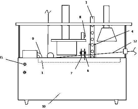
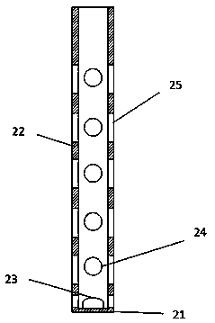
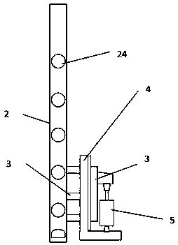
[0024] see figure 1 and figure 2 , the embodiment of the present invention includes:

[0025] An automatic tinning device for tinning equipment is provided, the tinning device includes: a tin pool 1, a tin filling module, an alarm module and a PLC control module; the PLC control module is installed in the control cabinet 10 below, the A tin pool heating device 9 and a liquid level monitor are installed on the tin pool 1, and the liquid level monitor is electrically connected to the PLC control module; the tin filling module includes a tin box 2 and a tin box driving device, and the tin box 2 is a box-shaped structure with an opening on one sid...


PUM


Abstract

The invention discloses an automatic tin adding device of tin plating equipment and a tin adding method. According to the automatic tin adding device, a tin block is arranged in a tin box with the bottom provided with a hollow liquid outlet, a PLC automatic control module is utilized for controlling the action of the tin box, and when tin supplementing is needed, the bottom of the tin box is vertically immersed in tin liquid, heat of a tin pond is utilized for melting the tin block, meanwhile, the melted part is gradually supplemented through gravity of the tin block, and after the tin pond iscompletely supplemented, the whole tin box is automatically lifted, the whole tin supplementing action is soft and continuous, and the liquid level of the tin pond is stable. Through the above manner, impacts on the liquid level of the tin pond during tin block adding can be reduced, generation of ripples is reduced, product tin plating layer thickness fluctuation is obviously reduced, and the product precision is obviously improved; and the tin supplementing structure is exquisite and can be embedded in the tin plating equipment, the occupied space is small, and the integral size of the tinplating equipment is reduced.

Description

technical field [0001] The invention relates to the field of tinning equipment, in particular to a tinning device of the tinning equipment. Background technique [0002] Nowadays, tin plating on the surface of copper wire or copper strip is generally performed by tin pool hot-dip tinning process. During hot-dip tinning, with the operation of the equipment, the tin liquid in the tin pool will be continuously consumed and needs to be replenished in time. The traditional method of replenishing liquid tin is to manually put long strips of tin directly into the tin pool, but this way of filling tin can cause safety hazards due to the high temperature of the tin pool on the one hand, and on the other hand, the judgment of the liquid level by human eyes is subjective. , not accurate enough, in addition to putting the whole piece of tin block directly will stir the liquid surface and cause a large shock, which will affect the surface quality of tinned products with higher requireme...

Claims


Application Information

Patent Timeline
Patent Type & Authority Applications(China)
IPC IPC(8): B23K3/00C23C2/08C23C2/36
CPCB23K3/00C23C2/08C23C2/36
Inventor 徐敏杰
Owner 江苏揽鑫新能源科技有限公司
Learn More