Workpiece stabilizing and fixing mechanism for machining grinding machine

A fixed mechanism and machining technology, applied in the direction of grinding workpiece supports, etc., can solve the problems of reducing the efficiency and accuracy of workpiece machining, workpiece machining errors, poor positioning effect, etc., to increase positioning effect, increase stability, increase The effect of precision

Active Publication Date: 2019-07-12
河南工学院
View PDF5 Cites 0 Cited by
  • Summary
  • Abstract
  • Description
  • Claims
  • Application Information

AI Technical Summary

Problems solved by technology

However, due to the different sizes of the processed workpieces, the existing stable and fixed mechanism for workpieces for machining grinding machines does not have the ability to locate workpieces of different sizes, and the positioning effect of the existing stable and fixing mechanisms for workpieces for machining and grinding machines is relatively low. Poor, it is easy to cause errors in workpiece processing, thereby reducing the efficiency and accuracy of workpiece processing, and increasing the cost of later reprocessing

Method used


Image

  • Workpiece stabilizing and fixing mechanism for machining grinding machine
  • Workpiece stabilizing and fixing mechanism for machining grinding machine
  • Workpiece stabilizing and fixing mechanism for machining grinding machine

Examples


Embodiment 1

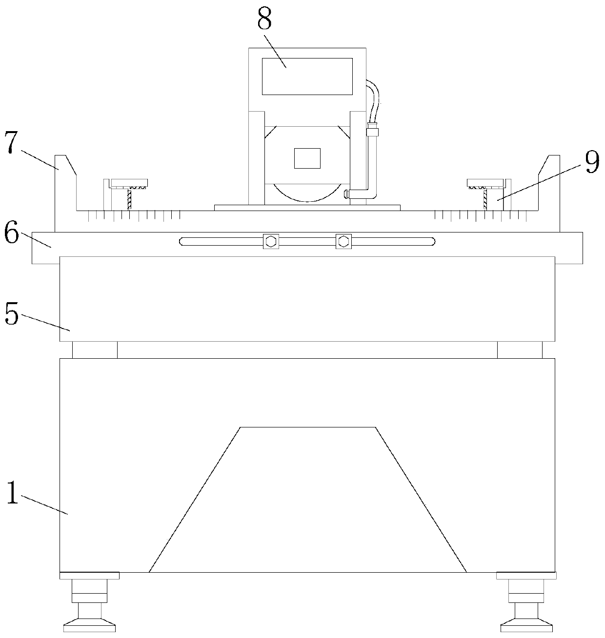
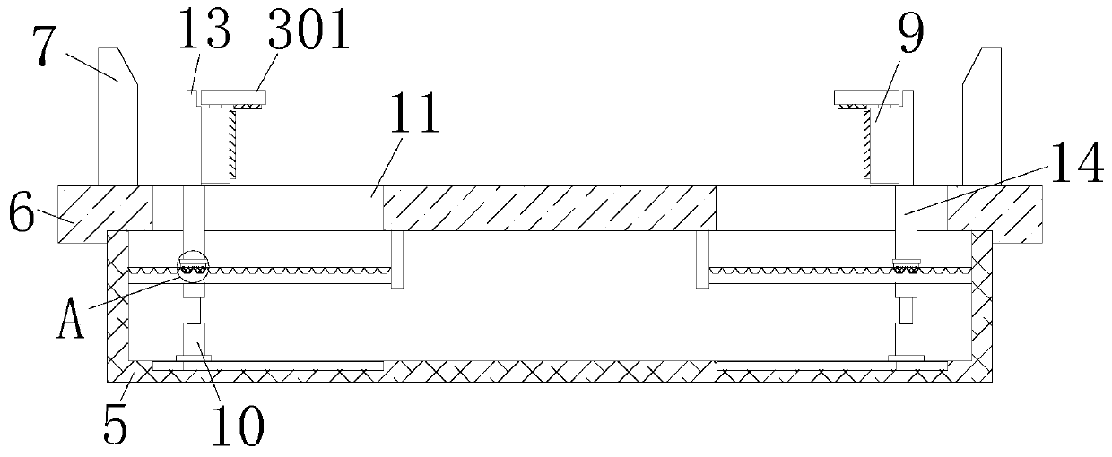
[0034] refer to Figure 1-9 , the stabilizing and fixing mechanism of workpieces for machining grinding machines of the present invention comprises a bottom box 1, the top of the bottom box 1 is fixedly connected with a fixed shell 5, the top of the fixed shell 5 is fixedly connected with a top plate 6, and the top of the top plate 6 is fixedly connected with a grinding wheel. Cutting equipment 8, both sides of top plate 6 top are all movably connected with movable plate 13, and the opposite side of two movable plates 13 is all fixedly connected with positioning shell 9, and the top of positioning shell 9 is movably connected with positioning mechanism 3, and positioning mechanism 3 The bottom of the top plate penetrates to the inner cavity of the positioning shell 9 and is fixedly connected with the inner wall of the positioning shell 9. The bottom of the movable plate 13 is fixedly connected with a slide plate 14, and both sides of the top plate 6 are provided with a first po...

Embodiment 2

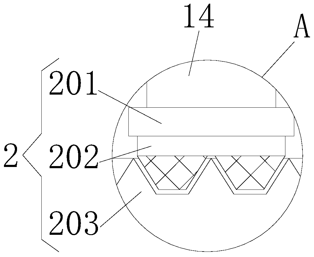
[0036] In a preferred embodiment, the limit mechanism 2 includes a limit plate 201, the rear side of the limit plate 201 is fixedly connected with the slide plate 14, the bottom of the limit plate 201 is fixedly connected with a block 202, and the two sides of the inner cavity of the fixed shell 5 Both sides are provided with clamping plates 203 used in conjunction with the clamping blocks 202 .

[0037] In a preferred embodiment, the positioning mechanism 3 includes a positioning plate 301, the bottom of the positioning plate 301 is fixedly connected with an engaging plate 302, the bottom of the engaging plate 302 penetrates into the inner cavity of the positioning shell 9 and is fixedly connected with a connecting block 303, the connecting block The bottom of 303 is fixedly connected with extension spring 304 , and the bottom of extension spring 304 is fixedly connected with the inner wall of positioning shell 9 .

[0038]In a preferred embodiment, the fixing mechanism 4 inc...

Embodiment 3

[0040] In a preferred embodiment, a positioning block is fixedly connected to the side of the clamping plate 203 away from the inner wall of the fixed shell 5 , and the top of the positioning block is fixedly connected to the inner wall of the fixed shell 5 . By arranging the limit mechanism 2, the effect of limiting the slide plate 14 is effectively realized, preventing the slide plate 14 from shaking left and right, thereby increasing the stability of the positioning shell 9 after adjustment, preventing the shaking of the positioning shell 9, thereby increasing The accuracy of workpiece processing is improved, and by setting the positioning block, the function of supporting and fixing the clamping plate 203 is effectively realized, thereby increasing the stability of the clamping plate 203. The surface of the connecting plate 302 is covered with a stabilizing sleeve, and the top of the stabilizing sleeve is fixedly connected with the inner wall of the positioning shell 9 , an...


PUM


Abstract

The invention discloses a workpiece stabilizing and fixing mechanism for a machining grinding machine. The workpiece stabilizing and fixing mechanism comprises a bottom box. The top of the bottom boxis fixedly connected with a fixed shell. The top of the fixed shell is fixedly connected with a top plate. The top of the top plate is fixedly connected with a grinding device. The two sides of the top of the top plate are both movably connected with movable plates. The opposite sides of the two movable plates are both fixedly connected with positioning shells. The top of each positioning shell ismovably connected with a positioning mechanism. The workpiece stabilizing and fixing mechanism for the machining grinding machine is provided with the bottom box, limiting mechanisms, the positioningmechanisms, fixing mechanisms, the fixed shell, the top plate, protection plates, the grinding device, the positioning shells, telescopic rods, first ports, springs, the movable plates, sliding plates, connecting plates, vertical plates, fixing grooves, second ports and pull rings to be used cooperatively. The problems that a user cannot conduct positioning on different sizes of workpieces conveniently through an existing machining grinding tool workpiece stabilizing and fixing mechanism and the positioning effect of the workpieces is poor are solved.

Description

technical field [0001] The invention relates to the technical field of mechanical processing, in particular to a stable fixing mechanism for workpieces used in mechanical processing grinding machines. Background technique [0002] Machining refers to the process of changing the shape or performance of a workpiece through a mechanical device. According to the difference in processing methods, it can be divided into cutting processing and pressure processing. [0003] Grinding machines are needed in mechanical processing. Grinding machines are machine tools that use abrasive tools to grind the surface of workpieces. Most grinding machines use high-speed rotating grinding wheels for grinding, and a few use other abrasive tools such as oil stones and abrasive belts. And free abrasives are processed, and the grinding machine for mechanical processing needs to position the workpiece when processing the workpiece. However, due to the different sizes of the processed workpieces, th...

Claims


Application Information

Patent Timeline
Patent Type & Authority Applications(China)
IPC IPC(8): B24B41/06
CPCB24B41/06
Inventor 翁楠王耀耀千红涛邓长城马晓杰
Owner 河南工学院
Why Eureka
Try Eureka