ambulance

A rescue vehicle and vehicle-driven technology, which is applied in the field of rescue vehicles, can solve problems such as slow movement of faulty rubber-tyred vehicles, long rescue time, and low rescue efficiency, and achieve the effects of shortening rescue time, reducing rescue costs, and improving rescue efficiency

Active Publication Date: 2021-03-30
CHINA SHENHUA ENERGY CO LTD +1
View PDF5 Cites 0 Cited by
  • Summary
  • Abstract
  • Description
  • Claims
  • Application Information

AI Technical Summary

Problems solved by technology

In the process of realizing the present invention, the inventor found that if the dragging method is used for rescue, the faulty rubber-tyred vehicle travels very slowly, the rescue time is long, the rescue efficiency is low, and the rescue cost is high

Method used


Image

  • ambulance
  • ambulance
  • ambulance

Examples


Embodiment 1

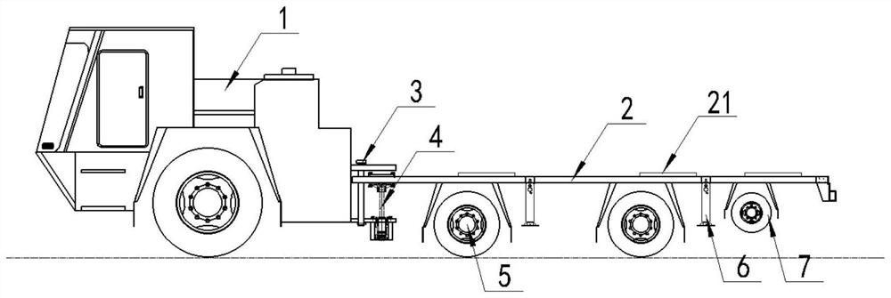
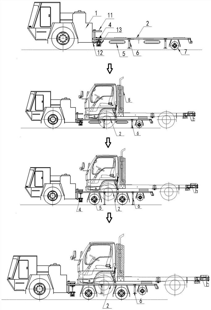
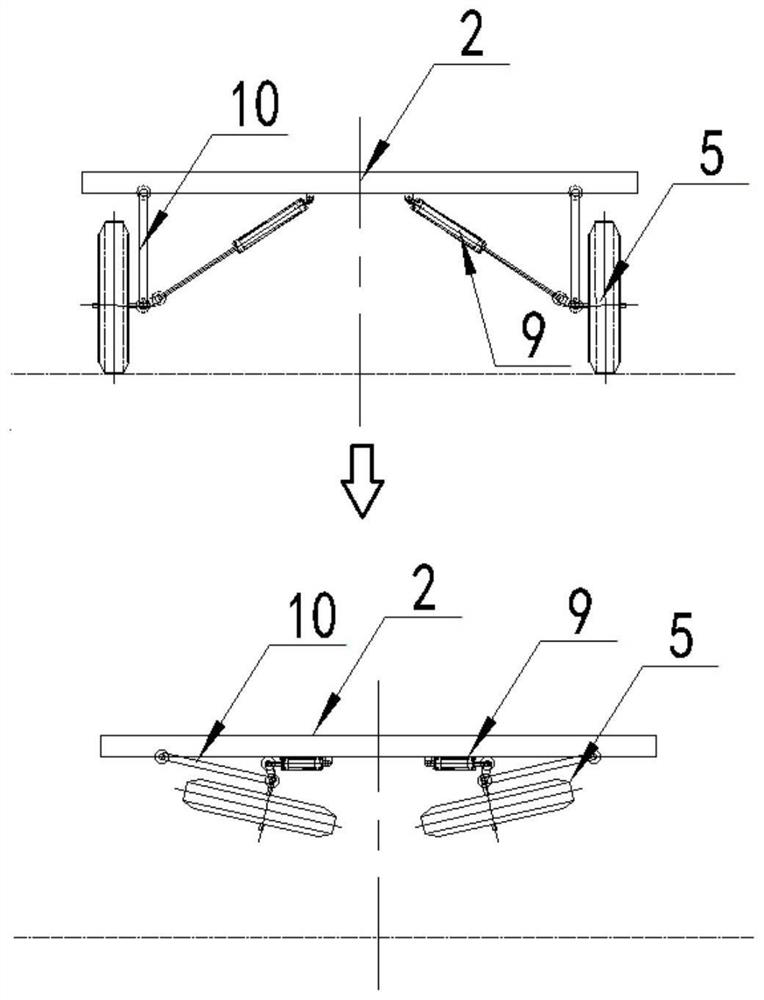
[0022] figure 1 A schematic structural diagram of a rescue vehicle according to an embodiment of the present invention is shown, figure 2 A working diagram of the rescue vehicle according to the embodiment of the present invention is shown, image 3 A working schematic diagram of the load-carrying wheel of the embodiment of the present invention is shown.

[0023] Such as Figure 1-3 As shown, the rescue vehicle provided by the embodiment of the present invention includes: a vehicle driving part 1, a support rod 10, a load-bearing wheel 5, a telescoping rod 9, auxiliary wheels 7, a lifting part 6 and a load-bearing platform 2 for transporting a faulty vehicle .

[0024] The lifting part 6 is installed on the carrying platform 2 and is used for lifting the carrying platform 2 . In this embodiment, the lifting part 6 can be a lifting cylinder.

[0025] The first end of the support rod 9 is hinged on the lower surface of the bearing platform facing the ground, and the beari...

Embodiment 2

[0035] On the basis of the first embodiment above, optionally, as image 3 As shown, the rescue vehicle also includes: a connecting rod.

[0036] Both ends of the connecting rod are respectively hinged to the telescopic end of the telescopic rod 9 and the second end of the supporting rod 10 . By setting the connecting rod, the retracted height of the load-bearing wheels 5 can be increased to facilitate the movement of the load-bearing platform 2 .

[0037] Optionally, the rescue vehicle further includes: a lifting cylinder 4 for lifting the carrying platform, and the lifting cylinder 4 is located between the load-bearing wheels 5 and the vehicle driving part 1 .

[0038] By arranging the lifting cylinder 4, the lifting stability of the bearing platform 2 can be improved to ensure the stable lifting of the bearing platform 2.

[0039] Further, the number of the lifting parts 6 is at least two, and the at least two lifting parts 6 are evenly distributed along the length direct...


PUM


Abstract

The embodiment of the invention discloses a rescue vehicle. The rescue vehicle comprises a vehicle driving part, supporting rods, load-bearing wheels, telescopic rods, auxiliary wheels, lifting partsand a bearing platform used for transporting fault vehicles, the lifting parts are mounted on the bearing platform and used for rising and falling the bearing platform, the first ends of the supporting rods are hinged to the bearing platform, the load-bearing wheels are rotatably mounted at the second ends of the supporting rods, the fixed ends of the telescopic rods are mounted on the bearing platform, the telescopic ends of the telescopic rods are connected with the load-bearing wheels, the auxiliary wheels are rotatably mounted on the bearing platform, the outer diameter of the auxiliary wheels are less than that of the load-bearing wheels, and the vehicle driving part drives the bearing platform to move through the load-bearing wheels or the auxiliary wheels. By utilizing the rescue vehicle, the time of transporting away from an accident scene of the fault vehicles can be shortened, the rescue time is shortened, the rescue efficiency is improved, the rescue cost is lowered, the structure is simple, and the production cost is low.

Description

technical field [0001] The invention relates to the technical field of automobiles, in particular to a rescue vehicle. Background technique [0002] With the continuous improvement of the mechanization of coal mine mining, a large number of rubber-tyred vehicles are used for personnel transportation and material handling in coal mines. Due to the limited underground space, once rubber-tyred vehicles fail to move due to failure, some panels will be affected. Even the transportation work of the whole mine not only brings economic losses to the mine, but also may bring other serious accidents to the mine. Therefore, it is necessary to rescue the faulty vehicle in time. [0003] Due to the space limitation of the coal mine underground roadway, the current mine rescue method for faulty rubber-tyred vehicles is mainly to be dragged by forklifts or rubber-tyred vehicles. In the process of realizing the present invention, the inventor found that if the dragging method is used for ...

Claims


Application Information

Patent Timeline
Patent Type & Authority Patents(China)
IPC IPC(8): B60P3/12B60P1/02
CPCB60P1/02B60P3/122
Inventor 潘吉成刘柄良杨英兵冯永伟
Owner CHINA SHENHUA ENERGY CO LTD
Why Eureka
Try Eureka