Vehicle safety control method based on tire condition information and vehicle

A state information and safety control technology, applied in the field of vehicle safety, can solve problems such as large background noise, large center of gravity deviation, slippage, etc., achieving the effect of small time complexity and space complexity, reducing energy consumption and improving execution efficiency.

Active Publication Date: 2019-07-12
中睿宏智汽车技术(深圳)有限公司
View PDF8 Cites 15 Cited by
  • Summary
  • Abstract
  • Description
  • Claims
  • Application Information

AI Technical Summary

Problems solved by technology

[0003] However, with the above-mentioned sensors and adhesion coefficient observation methods such as fuzzy neural network or synovial film variable structure, due to the extremely complex road conditions of the vehicle, various sensors are in dynamic changes all the time, not only there is a large background noise and various Interference, and the load in the vertical direction of the tire (for example, when braking, the center of gravity of the vehicle moves forward, and the deviation from the center of gravity in the static state is relatively large), and time-varying parameters such as wind resistance during vehicle driving cannot be obtained in real time. Parameters such as slip rate and adhesion coefficient not only have large errors, but also the algorithm is complex, robust and not real-time; using the "best slip rate" empirical value estimation method, the utilization rate of the adhesion coefficient of the vehicle cannot always be at the best state, the vehicle may lock up (in the case of braking) or slip (in the case of driving), and even cause the vehicle to become unstable.
At the same time, when the sensor performance changes or fails, it is difficult to be discovered and detected in time, which will undoubtedly bring serious safety hazards to the driving process of the vehicle.

Method used


Image

  • Vehicle safety control method based on tire condition information and vehicle
  • Vehicle safety control method based on tire condition information and vehicle
  • Vehicle safety control method based on tire condition information and vehicle

Examples


Embodiment 1

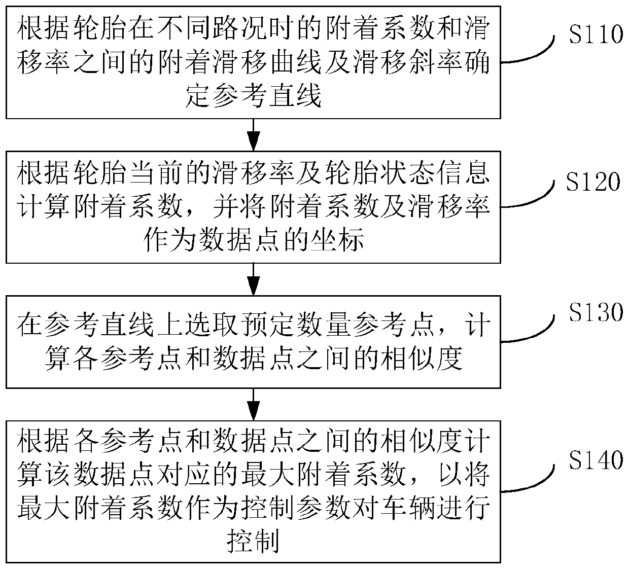
[0060] figure 1 A schematic flowchart of a vehicle safety control method based on tire state information provided by the first embodiment of the present invention is shown. The vehicle safety control method based on tire state information includes:

[0061] Step S110, determining a reference straight line according to the adhesion-slip curve and slip slope between the adhesion coefficient and slip rate of the tire under different road conditions.

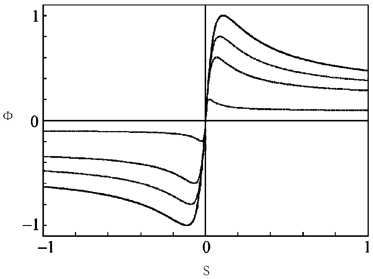
[0062] Specifically, the adhesion coefficient and slip rate of the vehicle under different road conditions can be collected, and the adhesion coefficient and slip rate of each road condition can be fitted into an adhesion-slip curve. Since the adhesion coefficient and slip rate of different road conditions are different, the adhesion-slip curves obtained by fitting different road conditions are also different.

[0063] Such as figure 2 Shown are the adhesion-slip curves of the tire under different road conditions, where Φ is the...

Embodiment 2

[0124] Figure 6 A schematic flowchart of a vehicle safety control method based on tire state information provided by the second embodiment of the present invention is shown. The vehicle safety control method based on tire state information includes the following steps:

[0125] Step S210, determining a reference straight line according to the adhesion-slip curve and slip slope between the adhesion coefficient and slip rate of the tire under different road conditions.

[0126] This step is the same as step S110 and will not be repeated here.

[0127] Step S220, calculating the adhesion coefficient according to the current tire slip ratio and tire state information, and using the adhesion coefficient and slip ratio as the coordinates of the data points.

[0128] This step is the same as step S120 and will not be repeated here.

[0129] Step S230, selecting a predetermined number of reference points on the reference straight line, and calculating the similarity between each r...

Embodiment 3

[0143] Figure 7 A schematic flowchart of a vehicle safety control method based on tire state information provided by the third embodiment of the present invention is shown. The vehicle safety control method based on tire state information includes the following steps:

[0144] Step 310, determining a reference straight line according to the adhesion-slip curve and slip slope between the adhesion coefficient and slip rate of the tire under different road conditions.

[0145] This step is the same as step S110 and will not be repeated here.

[0146] Step 320, calculating the adhesion coefficient according to the current tire slip ratio and tire state information, and using the adhesion coefficient and slip ratio as the coordinates of the data points.

[0147] This step is the same as step S120 and will not be repeated here.

[0148] Step S330, selecting a predetermined number of reference points on the reference straight line, and calculating the similarity between each refe...


PUM


Abstract

The invention discloses a vehicle safety control method based on tire condition information and a vehicle. The vehicle safety control method includes the steps that a reference line is determined according to an adhesion slip curve between an adhesion coefficient and the slip rate and the slip slope of tires under different road conditions; the adhesion coefficient is calculated according to the current slip slope of the tires and tire condition information, and the adhesion coefficient and the slip slope are taken as coordinates of data points; a predetermined number of reference points are selected on the reference line, and the similarity between the reference points and the data points is calculated; and maximum adhesion coefficients corresponding to the data points are calculated according to the similarity between the reference points and the data points, and the maximum adhesion coefficients are taken as control parameters to control the vehicle. According to the technical scheme, the maximum adhesion coefficients of the tires in the vehicle are calculated in real time and accurately, thus the maximum effective braking force or effective driving force is obtained, the driving safety of the vehicle is improved, and energy consumption of the vehicle is decreased.

Description

technical field [0001] The present invention relates to the technical field of vehicle safety, in particular to a vehicle safety control method based on tire state information and a vehicle. Background technique [0002] In the existing field of vehicle active safety, various parameter information during vehicle driving is collected mainly through empirical value estimation methods or through various sensors (such as identifying the driver's driving position through the steering wheel angle sensor and each wheel speed sensor). direction, through the yaw rate sensor to identify the rotation angle of the vehicle around the direction perpendicular to the ground axis and the lateral acceleration sensor to identify the actual direction of movement of the vehicle, etc.), and then calculate parameters such as slip rate and adhesion coefficient through the collected various complex parameter information , through the calculated parameters to selectively brake or drive the vehicle to...

Claims


Application Information

Patent Timeline
Patent Type & Authority Applications(China)
IPC IPC(8): B60W40/12
CPCB60W40/12
Inventor 周开伟周海忠李国莲周丽莎
Owner 中睿宏智汽车技术(深圳)有限公司
Why Eureka
Try Eureka