
Mechanical deviation measuring instrument based on drilling fluid circulation
A drilling fluid circulation and mechanical technology, applied in the field of drilling, can solve the problems of no research reports, etc., and achieve the effects of avoiding large construction errors, low use cost, and easy correction and treatment
- Summary
- Abstract
- Description
- Claims
- Application Information
AI Technical Summary
Problems solved by technology
Method used
Image

Examples
Embodiment 1
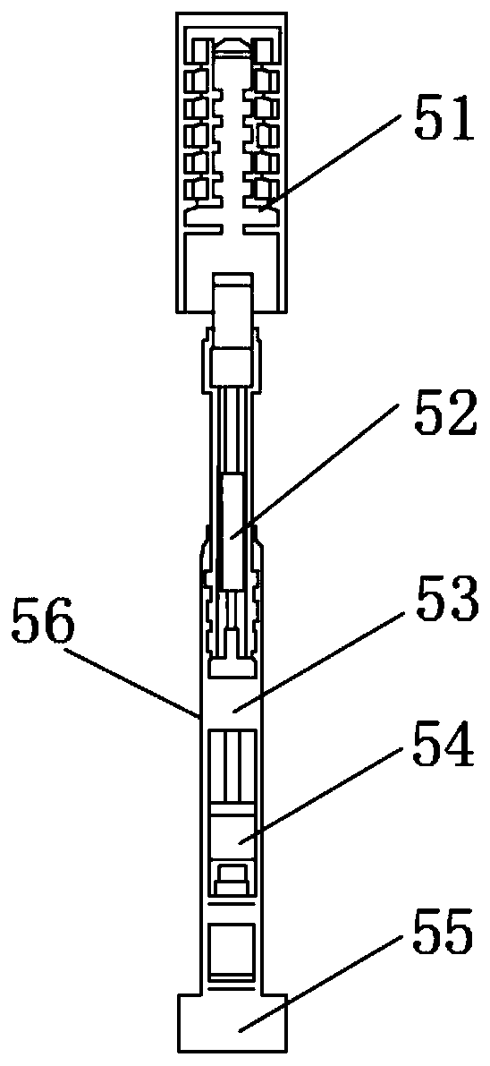
[0032] Such as figure 1 As shown, in this embodiment, a mechanical inclinometer based on drilling fluid circulation includes a pulse generating device 51, an encoding control mechanism 52, an inclinometer mechanism 53, a damping device 54 and a The drill bit communicates with the base 55, and the base 55 is provided with a casing 56 covering the damping device 54, the inclinometer mechanism 53 and the coding control mechanism 52. The base 55 is used to provide an installation base for the installation of the drill bit. Use the inclinometer mechanism 53 to measure the degree of well inclination, use the code control mechanism 52 to code the data measured by the inclinometer mechanism 53, and use the pulse generator 51 to convert the code of the code control mechanism 52 into a pulse signal for output.
[0033]The inclinometer instrument adopts a mechanical structure. During the drilling process, it can realize the measurement while drilling to detect the downhole parameters. I...
Embodiment 2
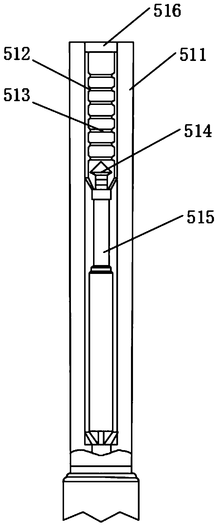
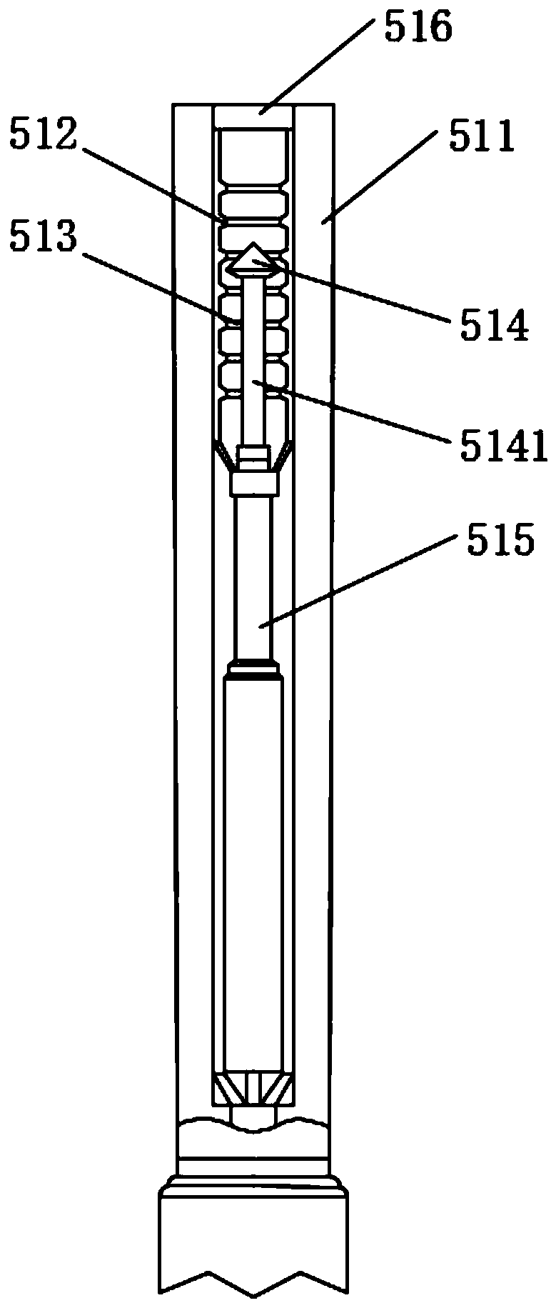
[0036] Such as figure 2 , image 3 As shown, on the basis of the above embodiments, in this embodiment, the pulse generating device 51 includes a pulse ring 511 communicated with the casing 56, several joints arranged in the pulse ring 511 and coaxial with the pulse ring 511 The flow ring 512, the pulse rod 515 arranged in the pulse ring 511, the pulse rod 5141 located in the pulse ring 511 and slidingly connected with the pulse rod 515, the pulse valve 514 connected with the pulse rod 5141, and the middle part of the throttle ring 512 It is an orifice 513 coaxial with the pulse ring 511 . The pulse generating device 51 is provided with a connecting hole 516 communicating with the drill collar 9.
[0037] When the drilling fluid pumped by the pump 1 enters the pulse ring 511, the pulse valve 514 moves downward under the action of the drilling fluid. When the pulse valve 514 passes through the orifice 513, the flow area of the drilling fluid changes from large to small. W...
Embodiment 3
[0053] Such as Figure 8 As shown, on the basis of the above embodiments, in this embodiment, the damping device 54 includes a damping outer cylinder 541 arranged in the housing 56 and having a through hole, and is slidably arranged on the damping outer cylinder 541 close to the inclinometer mechanism. The damping pulse rod 543 at one end of the mechanism 53, the damping valve 542 arranged in the damping outer cylinder 541, and the damping piston 544 slidingly arranged in the damping outer cylinder 541, the damping piston 544 and the damping pulse rod 543 are respectively located at the damping valve 542 both ends.
[0054] The damping outer cylinder 541 is filled with lubricating oil, and the damping pulse rod 543 tends to move downward under the impact force of the drilling fluid. Since the hydraulic oil is incompressible, the pressure of the upper cavity in the damping outer cylinder 541 rises. When the pressure difference between the upper cavity and the lower cavity is s...
PUM
 Abstract
Description
Claims
Application Information