Mine intrinsic safety type camera

An intrinsically safe camera technology, applied in the field of cameras, can solve problems such as waste of resources, inconvenient observation and repair, and small internal space of the camera, and achieve the effects of reducing difficulty, facilitating manual replacement and repair, and facilitating observation and repair

Active Publication Date: 2019-07-12
安徽玄离智能科技股份有限公司
View PDF17 Cites 2 Cited by
  • Summary
  • Abstract
  • Description
  • Claims
  • Application Information

AI Technical Summary

Problems solved by technology

[0003] There are certain drawbacks in the existing intrinsically safe camera for mine use, (1), when repairing the internal device of the camera, it is necessary to use tools to remove the shell of the camera, and then repair and repair the various parts inside the device. Inspection, because each component is installed inside the camera, and the internal space of the camera is small, it is inconvenient to observe and repair, and secondly, due to the compact installation of each component and the intricate wiring, it further increases the difficulty of repair; (2), Since the mining camera needs to be used in the mine for a long time, and the light in the mine is insufficient, it is necessary to install lighting equipment to supplement the shooting of the camera, and in order to cooperate with the work of the camera, the lighting equipment needs to be illuminated for a long time to reduce the LED light. Second, the installation of LED lamps in existing lighting equipment is fixed with the circuit board by soldering. When one or more LED lamps are damaged, there are two methods. One is to repair the circuit board. Replacement of the board as a whole, because the other LED lights are not damaged, the overall replacement will cause a certain waste of resources; another method is to remove the damaged LED lights first, and then re-solder the new LED lights, this process is too cumbersome, cutting It is easy to cause damage to the circuit board. Therefore, we propose a mining intrinsically safe camera

Method used


Image

  • Mine intrinsic safety type camera
  • Mine intrinsic safety type camera
  • Mine intrinsic safety type camera

Examples


Embodiment Construction

[0023] In order to make the technical means, creative features, goals and effects achieved by the present invention easy to understand, the present invention will be further described below in conjunction with specific embodiments.

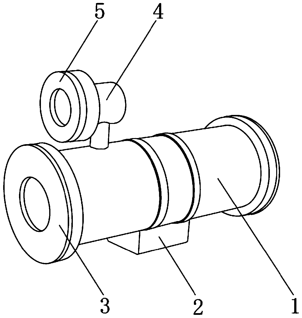
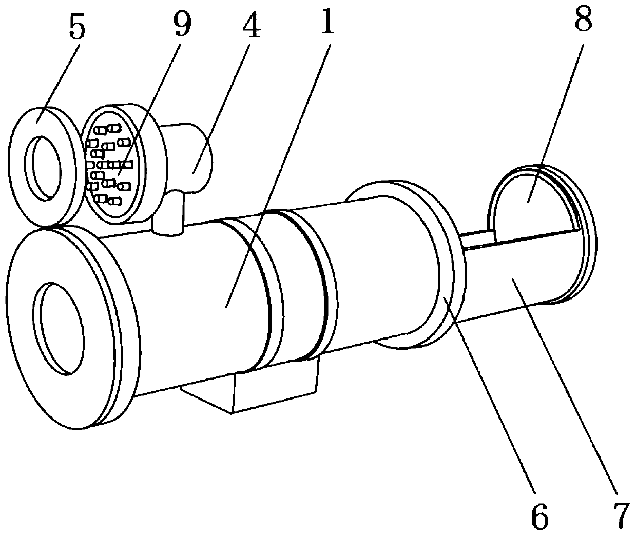
[0024] refer to Figure 1-2 As shown, a mining intrinsically safe camera includes a camera tube 1, the outer surface of the camera tube 1 is fixed with a control box 2 through a throat clamp near the bottom end, and the front end outer surface of the camera tube 1 is welded with a front fixing ring 3 , and the inner center of the front fixing ring 3 is bonded with a lens near the front end, the outer surface of the front end of the front fixing ring 3 near the lens is fixed with a dust-proof net by bolts, and the outer surface of the top of the camera 1 is welded near the front end There is a lamp tube 4, and the outer surface of the front end of the lamp tube 4 is fixed with a lampshade 5 by bolts, the outer surface of the rear end of the camera ...


PUM


Abstract

The invention discloses a mine intrinsic safety type camera which comprises a camera barrel, wherein a control box is fixedly installed on the outer surface, near the bottom end, of the camera barrelthrough a hose clamp; a front fixing ring is welded to the outer surface of the front end of the camera barrel; and a lens is adhered to the inner center, near the front end, of the front fixing ring.According to the mine intrinsic safety type camera, parts in a camera body are installed in a part mounting box in advance, and a sliding rail is installed between the part mounting box and the camera barrel, so that the part mounting box can slide out together with the parts installed in the part mounting box, thereby facilitating observation and repair by repairers and reducing the repair difficulty of the device; and a positive copper sheet and a negative copper sheet are installed in a circuit board correspondingly, magnet sheets are installed between the copper sheets and pins, and the pins of LED lamps are connected with the circuit board through the magnet sheets, so that the damaged LED lamps are convenient to manually replace and repair, and simplicity and convenience are achieved.

Description

technical field [0001] The invention relates to the field of cameras, in particular to an intrinsically safe camera for mine use. Background technique [0002] With the application and popularization of roadway intelligent technology, the technology of installing cameras in mines and underground working equipment and other mining machinery for remote visual monitoring of roadway operations has also developed rapidly; [0003] There are certain drawbacks in the existing intrinsically safe camera for mine use, (1), when repairing the internal device of the camera, it is necessary to use tools to remove the shell of the camera, and then repair and repair the various parts inside the device. Inspection, because each component is installed inside the camera, and the internal space of the camera is small, it is inconvenient to observe and repair, and secondly, due to the compact installation of each component and the intricate wiring, it further increases the difficulty of repair;...

Claims


Application Information

Patent Timeline
Patent Type & Authority Applications(China)
IPC IPC(8): E21F17/18E21F17/00H04N5/225
CPCE21F17/18E21F17/00H04N23/51
Inventor 郭延达
Owner 安徽玄离智能科技股份有限公司
Why Eureka
Try Eureka