Compressor vortex reducing structure with cascade type de-rotation nozzles

A technology of compressors and nozzles, which is applied in the direction of gas turbine devices, mechanical equipment, machines/engines, etc., which can solve the problems of small nozzle inlet flow area, increased nozzle inlet flow loss, and enhanced flow separation, so as to reduce the air flow backflow area and reduce the Effect of pressure loss and flow resistance reduction

Inactive Publication Date: 2019-07-12
NANJING UNIV OF AERONAUTICS & ASTRONAUTICS
View PDF6 Cites 4 Cited by
  • Summary
  • Abstract
  • Description
  • Claims
  • Application Information

AI Technical Summary

Problems solved by technology

[0003] At present, the cross-section of the tubeless vortex reducer nozzle is usually circular, the flow area of ​​the nozzle inlet is small, and there will be a certain airflow turning angle when the upstream disc cavity gas enters the nozzle, so that the flow separation is enhanced, and the adverse consequences are increased Nozzle inlet flow loss

Method used


Image

  • Compressor vortex reducing structure with cascade type de-rotation nozzles
  • Compressor vortex reducing structure with cascade type de-rotation nozzles
  • Compressor vortex reducing structure with cascade type de-rotation nozzles

Examples


Embodiment Construction

[0018] In order to make the object, technical solution and advantages of the present invention clearer, the present invention will be further described in detail below in conjunction with specific embodiments and with reference to the accompanying drawings.

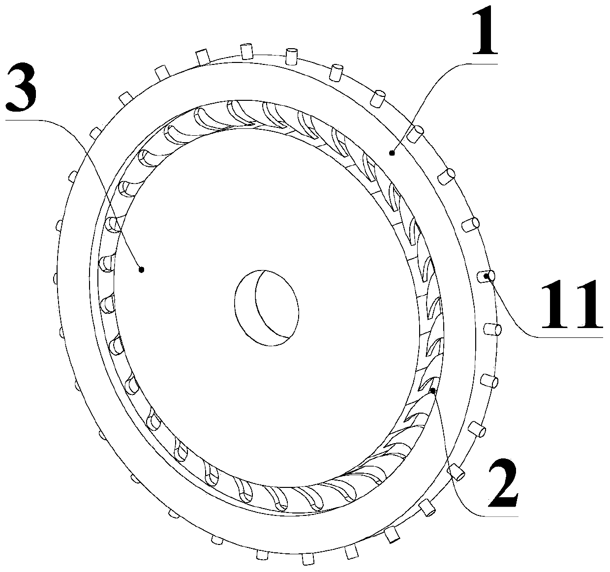
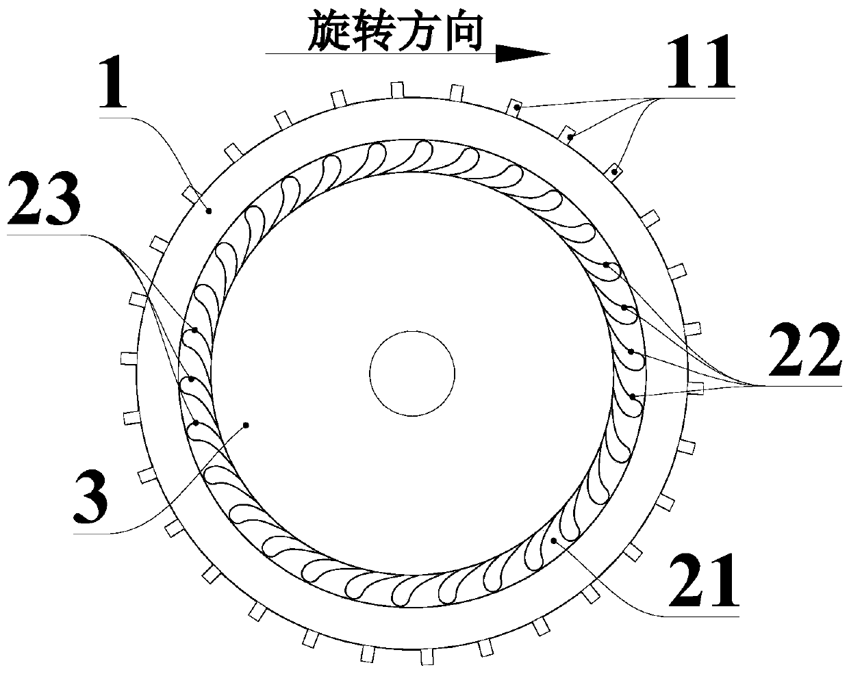
[0019] Such as figure 1 As shown, a compressor vortex reduction structure with cascade deswirling nozzles includes an upstream disc chamber 1, a vortex reduction unit 2 and a downstream disc chamber 3 that are sequentially connected from outside to inside and can rotate synchronously. The upstream disc chamber 1 A plurality of drum holes 11 fixed in the radial direction of the upstream disk cavity are arranged in the circumferential direction, and the vortex reducing unit 2 includes a plurality of nozzles 21 arranged in the axial direction, and the air flow in the compressor (not shown) flows from the drum to The hole 11 enters the upstream disk chamber 1 and follows the rotation of the upstream disk chamber 1 and enters ...


PUM


Abstract

The invention provides a compressor vortex reducing structure with cascade type de-rotation nozzles. The compressor vortex reducing structure comprises an upstream disc cavity, a vortex reducing unitand a downstream disc cavity which are sequentially connected from outside to inside and can synchronously rotate, wherein the upstream disc cavity is provided with a plurality of drum holes which areradially fixed along the upstream disc cavity in the circumferential direction; and the vortex reducing unit comprises the plurality of nozzles arranged in the axial direction, the airflow in a compressor enters the upstream disc cavity via the drum holes and then rotates along with the upstream disc cavity and enters the nozzles, and the airflow can move into the downstream disc cavity in the nozzles in the direction opposite to the rotation direction of the upstream disc cavity. The vortex reducing structure with the de-rotation nozzles has the advantages that the air intake area of the nozzles is large, and each inlet is an arc-shaped surface, so that the airflow is able to smoothly enter the nozzles, flow resistance is reduced, and pressure loss is reduced.

Description

technical field [0001] The invention relates to the technical field of de-swirling and cooling of the secondary air system of a gas turbine on the bottom surface and an aero-engine, in particular to a de-swirling and vortex-reducing structure of a compressor. Background technique [0002] Due to the rotation effect, the cold air drawn out by the compressor generates eddy currents during the radial inflow process in the rotating disk cavity, resulting in a decrease in pressure. The cold air pressure is directly related to the cooling of high-temperature components, the sealing of interstages and the cooling and sealing of bearing chambers, which is of great significance to improving engine performance and reliability. [0003] At present, the cross-section of the tubeless vortex reducer nozzle is usually circular, the flow area of ​​the nozzle inlet is small, and there will be a certain airflow turning angle when the upstream disc cavity gas enters the nozzle, so that the flo...

Claims


Application Information

Patent Timeline
Patent Type & Authority Applications(China)
IPC IPC(8): F02C3/08F04D29/44F04D29/66
CPCF02C3/08F04D29/444F04D29/667
Inventor 王锁芳郝媛慧夏子龙郑笑天
Owner NANJING UNIV OF AERONAUTICS & ASTRONAUTICS
Why Eureka
Try Eureka