
Clutch control apparatus

A technology of clutch control and clutch device, applied in mechanical control device, clutch, transmission control and other directions, can solve the problem of not allowing downshift, the driver cannot downshift, etc., and achieve the effect of suppressing transmission delay

Inactive Publication Date: 2019-07-12
HONDA MOTOR CO LTD
View PDF5 Cites 0 Cited by
  • Summary
  • Abstract
  • Description
  • Claims
  • Application Information

AI Technical Summary

Problems solved by technology

[0005] However, in conventional control, downshifting is not permitted when the engine speed is equal to or higher than a predetermined high speed, so there is a possibility that the driver cannot downshift at the desired timing.

Method used


Image

  • Clutch control apparatus
  • Clutch control apparatus
  • Clutch control apparatus

Examples


Embodiment Construction

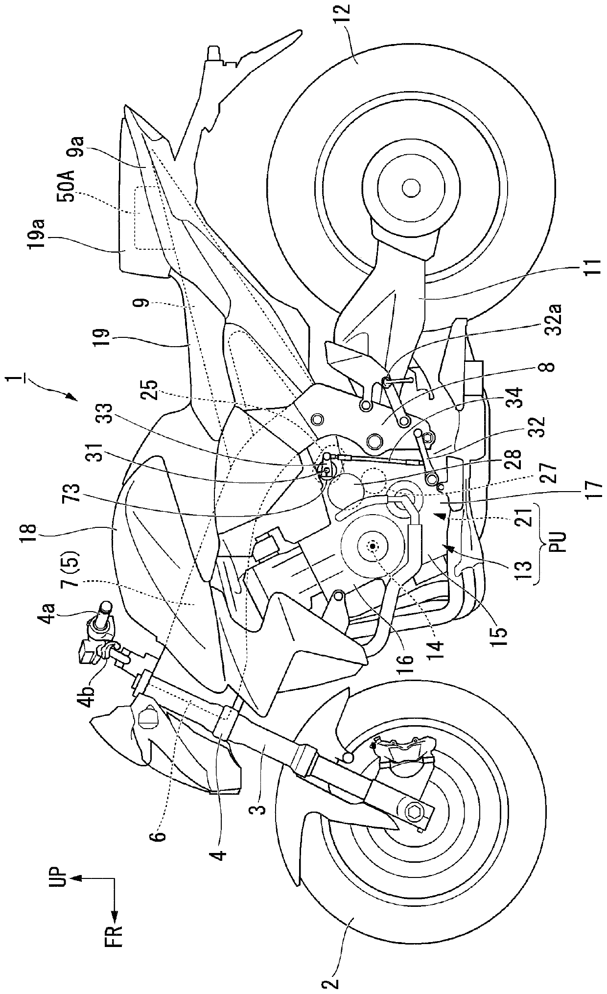
[0027] Hereinafter, embodiments of the present invention will be described with reference to the drawings. It should be noted that directions such as front, rear, left, and right in the following description are the same as the directions for the vehicle described below unless otherwise specified. In addition, an arrow FR indicating the front of the vehicle, an arrow LH indicating the left side of the vehicle, and an arrow UP indicating the upward direction of the vehicle are shown at appropriate positions in the drawings used in the following description.

[0028]

[0029] Such as figure 1 As shown, this embodiment is applied to the motorcycle 1 which is a straddle-type vehicle. Front wheels 2 of the motorcycle 1 are supported by lower end portions of a pair of left and right front forks 3 .

[0030] Upper portions of the left and right front forks 3 are supported by a head pipe 6 at a front end portion of a vehicle frame 5 via a steering column 4 . On the top bridge of ...


PUM


Abstract

A clutch control device includes an engine, a gearbox, a clutch device configured to disconnect and connect power transmission between the engine and the gearbox, a clutch actuator configured to drivethe clutch device and vary a clutch capacity, and an ECU configured to calculate a control target value of the clutch capacity, and the ECU determines whether an engine rotational number after downshifting by the gearbox enters a high rotation region and decreases the clutch capacity after downshifting when it is determined that the engine rotational number after downshifting enters the high rotation region.

Description

[0001] This application claims priority based on Japanese Patent Application No. 2017-254248 for which it applied on December 28, 2017, and uses the content here. technical field [0002] The invention relates to a clutch control device. Background technique [0003] Conventionally, a structure including a clutch device for disconnecting or connecting power transmission between an engine and a transmission is known (for example, refer to JP-A-60-139960). [0004] Japanese Patent Application Laid-Open No. 60-139960 describes a control that permits the execution of a downshift when the engine speed is lower than a predetermined high speed. This prevents over-revolution (ultra-high speed rotation) after a downshift. [0005] However, in the conventional control, the execution of the downshift is not permitted when the engine speed is equal to or higher than a predetermined high speed, and therefore there is a possibility that the driver cannot perform the downshift at the desi...

Claims


Application Information

Patent Timeline
Patent Type & Authority Applications(China)
IPC IPC(8): F16H61/02F16H61/40F16H63/32
CPCF16H61/02F16H61/40F16H63/32F16D48/02F16D48/06F16D2500/3067F16D2500/31466F16D2500/50287F16D2500/5046F16H63/46F16D48/066F16D2500/1026F16D2500/10412F16D2500/1045F16D2500/1117F16D2500/30806F16D2500/70406F16D2500/7044
Inventor 龙崎达也小野惇也大关孝
Owner HONDA MOTOR CO LTD
Learn More