

Runoff water sample collecting device
A collection device and collection device technology, which is applied in the direction of sampling devices, etc., can solve the problems of manual dependence, etc., and achieve the effects of stable and reliable structure, high degree of operation automation, and convenient transportation
- Summary
- Abstract
- Description
- Claims
- Application Information
AI Technical Summary
Problems solved by technology
Method used
Image

Examples
Embodiment 1
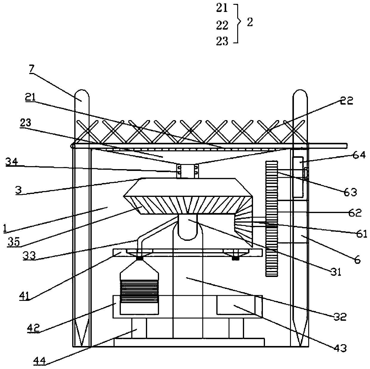
[0031] Example 1, such as figure 1 As shown, a runoff water sample collection device includes a sampling box 1 , a filtering and collecting device 2 inside the sampling box 1 , a water sample packing device 3 , a sampling bottle device and a driving device 6 .
[0032] The filtering and collecting device 2 is located on the top of the sampling box 1, and is used to filter the water flow and improve the sample quality. Specifically, the filter collection device 2 includes a first filter device 22 located on the uppermost floor and one side hinged to the sampling box 1, a second filter device 21 located in the middle, and a funnel-shaped confluence tank 23 located below the second filter device 21, The size of the filter holes of the second filter device 21 is smaller than that of the first filter device 22 .
[0033] The water sample dispensing device 3 comprises a rotary bin provided with an annular ring gear 35 at the bottom, a rotating support column 32 positioned at the bo...
Embodiment 2
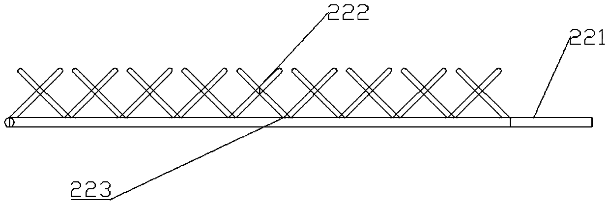
[0037] Embodiment 2, on the basis of embodiment 1, as figure 2As shown, the first filter device 22 includes a first filter plate 223 and several cross-distributed vertical rods 222 above the first filter plate 223, and the second filter device 21 has a smaller aperture than the first filter plate 223. Pore size of the second filter plate. The vertical rod 222 is arranged above the first filter plate 223, which can prevent the washed leaves from covering the filter plate below, causing most of the runoff to flow directly above the sampling device. As preferably, the active side of the first filter plate 223 shown (i.e. figure 2 The right side in) is also provided with handle 221.
Embodiment 3
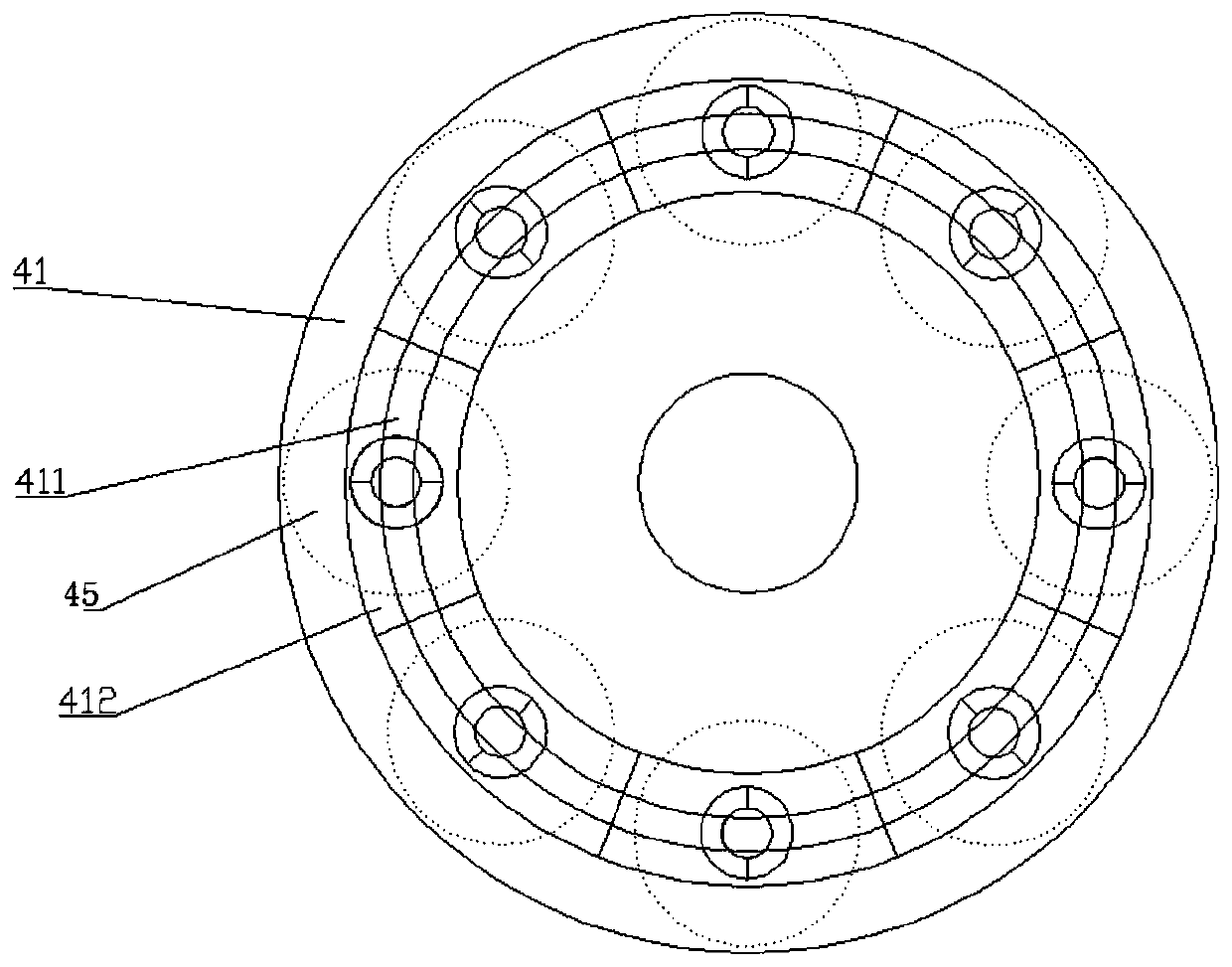
[0038] Embodiment 3, in order to avoid that the water sample flowing out of the draft tube 33 cannot accurately enter the sampling bottle 45, on the basis of Embodiment 1 or Embodiment 2, the sampling bottle device described in this embodiment also includes a Rotating support beam 32 is fixedly socketed with a limit deflector 41. The top surface of the limit deflector 41 is provided with an annular limit groove 411 suitable for the circular movement of the flow guide tube 33, and the bottom surface is provided with an annular limit groove. 411 runs through and is opposite to a plurality of water outlet holes of the sampling bottle 45 bottlenecks below, the bottleneck of the sampling bottle 45 is screwed with the water outlet hole of the limiting deflector 41, and the limiting deflector 41 can be connected to the flow guide tube 33. The trajectory of the movement is accurately limited, and the water sample is accurately flowed into the sampling bottle 45 through the water outlet...
PUM
 Abstract
Description
Claims
Application Information