
Switchgear operating state management monitoring system, method and computing device

A technology for operating status and switchgear, applied in computing, CCTV systems, computer parts, etc., to solve problems such as equipment and personnel injuries, poor visibility, and switchgear failures

Active Publication Date: 2021-09-03
西安图玛智能科技有限公司
View PDF8 Cites 0 Cited by
  • Summary
  • Abstract
  • Description
  • Claims
  • Application Information

AI Technical Summary

Problems solved by technology

During the opening and closing process, each device needs to cooperate with each other to complete the opening and closing of the switch. If the equipment fails or the coordination is not in place, it will cause the switch cabinet to fail, causing equipment and personnel injury. Therefore, it is very necessary to check the operating status of the switch cabinet. real-time monitoring
[0004] At present, the monitoring of the operating state of the switchgear mainly relies on various electrical sensors, which rely on monitoring various electrical signals to indirectly determine the working state of the switchgear, and the amount of monitored states is small and the visibility is poor.

Method used


Image

  • Switchgear operating state management monitoring system, method and computing device
  • Switchgear operating state management monitoring system, method and computing device
  • Switchgear operating state management monitoring system, method and computing device

Examples


Embodiment 1

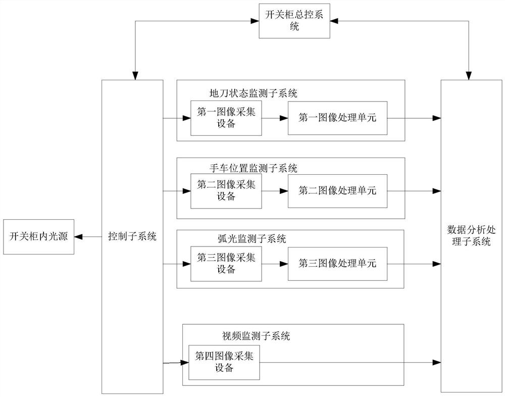
[0071] This embodiment discloses a switchgear operating state management and monitoring system, such as figure 1 As shown, it includes the control subsystem, ground knife status monitoring subsystem, handcart position monitoring subsystem, arc light monitoring subsystem, video monitoring system and data analysis and processing subsystem. In this embodiment, the control subsystem and the data analysis and processing subsystem are connected to the switchgear master control system to realize communication with the switchgear master control system.

[0072] The ground knife state monitoring subsystem includes a first image acquisition device and a first image processing unit; wherein:

[0073] The first image acquisition device is used to collect the image of the ground knife with marking points in the switch cabinet; before the image is collected, the marking points are arranged on the ground knife. The marking points can be set as circles, and their colors can be red or blue. ,...

Embodiment 2

[0105] This embodiment discloses a method for managing and monitoring the operating state of a switchgear, including the steps of ground knife state monitoring, handcart position monitoring, arc light monitoring, and video monitoring, wherein:

[0106] The ground knife status monitoring steps are:

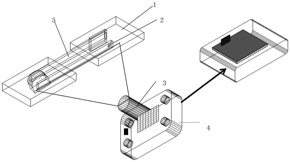
[0107] Step S11, collect the ground knife image corresponding to the ground knife with marked points in the switch cabinet through the first image acquisition device; in this embodiment, the number of marked points on the ground knife can be 1 or 2, and the local knife The number of 2 marking points on the board is 1, and the marking point can be set on the ground knife moving contact 5; when there are 2 marking points, the two marking points can be respectively set on the moving contact and the static contact, where The marking point on the moving contact is at the top of the moving contact, and the marking point on the static contact is at the top of the static contact; when ther...

Embodiment 3

[0159] This embodiment discloses a computing device, including a processor and a memory for storing executable programs of the processor. When the processor executes the program stored in the memory, the method for managing and monitoring the operating state of the switchgear described in Embodiment 2 is implemented. , specifically: including the ground knife state monitoring step, the handcart position monitoring step and the arc light monitoring step, wherein:

[0160] The ground knife status monitoring steps are:

[0161] The first image acquisition device is used to collect the ground knife image provided with the marking point in the switch cabinet;


PUM


Abstract

The invention discloses a switchgear operating state management monitoring system, method and computing equipment, including ground knife status, handcart position and arc monitoring; The knife image recognizes the current position of the ground knife, and determines whether the ground knife is currently in the opening state or the closing state; in the handcart position monitoring, the handcart image currently collected by the second image acquisition device is used to identify the position of the handcart. Position, to determine whether the handcart is currently moving to the opening or closing state. In the arc light monitoring, there is no contact image under lighting in the switch cabinet currently collected by the third image acquisition device and the third image acquisition device. The comparison results of the gray feature values ​​between the collected contact images where the arc phenomenon occurs can determine whether the arc phenomenon currently occurs; the present invention monitors the operating state of the switch cabinet in real time in a non-contact manner, and can realize the monitoring of the operating state of the switch cabinet. Accurate monitoring.

Description

technical field [0001] The invention belongs to the field of electric power measurement, and in particular relates to a management and monitoring system, method and computing equipment for the operating state of a switchgear. Background technique [0002] Switchgear is an important electrical equipment in the power system. It plays the role of opening and closing, controlling and protecting electrical equipment in the process of power system power generation, transmission, distribution and power conversion. It is used in power plants, substations, petrochemical, There are a large number of applications in various occasions such as metallurgy and steel rolling, light industry textiles, factories and mines, residential quarters, and high-rise buildings. [0003] The interior of the switchgear contains circuit breakers, disconnectors, load switches, operating mechanisms, transformers and various protection devices. During the opening and closing process, each device needs to c...

Claims


Application Information

Patent Timeline
Patent Type & Authority Patents(China)
IPC IPC(8): G06K9/00H04N7/18H04N5/235
CPCH04N7/181G06V20/41G06V20/46H04N23/74
Inventor 齐建辉马沁威陆勇王海波
Owner 西安图玛智能科技有限公司
Learn More