Contactor

A contactor and moving contact technology, applied in relays, electromagnetic relays, electromagnetic relay details and other directions, can solve the problems of affecting service life, complex structure, large wear, etc., to extend service life, improve reliability, and reduce loss Effect

Active Publication Date: 2019-07-12
李兵
View PDF9 Cites 0 Cited by
  • Summary
  • Abstract
  • Description
  • Claims
  • Application Information

AI Technical Summary

Problems solved by technology

[0005] Therefore, the technical problem to be solved by the present invention is to overcome the technical defects of the mechanical holding contactor in the prior art, such as relatively large structural wear, affecting service life, high cost and complex structure, so as to provide an energy-saving, simple structure, Contactor with low manufacturing cost, long service life and easy maintenance

Method used


Image

  • Contactor
  • Contactor
  • Contactor

Examples


Embodiment 1

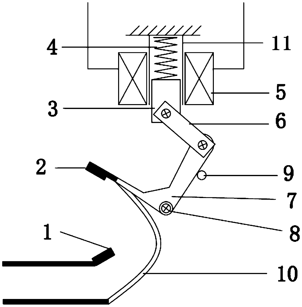
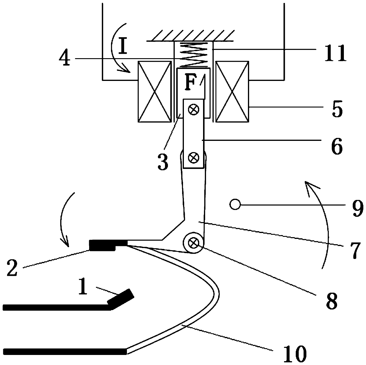
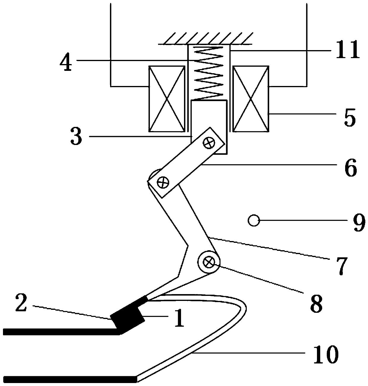
[0038] Such as figure 1 A specific implementation of the contactor shown in -3, including: iron core 3, electromagnetic coil 5 arranged on the outer periphery of iron core 3, swing structure 7 swinging along fixed axis 8, swinging direction along the swinging structure 7 The static contact 1 and the limit structure 9 are respectively arranged at the maximum swing range on both sides thereof.

[0039] The first end of the iron core 3 along its moving direction is provided with an elastic member 4, the elastic member 4 is in a compressed state, the other end of the elastic member 4 abuts against a fixed structure 11, and the second end of the iron core 3 The end is hinged with connecting rod 6. In this embodiment, when the electromagnetic coil 5 is energized, the iron core 3 overcomes the first elastic force of the elastic member 4 and moves in a direction away from the fixed shaft 8 under the action of the upward magnetic field force, that is, drives the connecting rod 6 to ve...

Embodiment 2

[0048] Such as Figure 4 As shown in -6, the swing structure 7 is a semicircular runner, the hinge point of the connecting rod 6 and the swing structure 7 is located on the axis of the semicircular runner, and the movable contact 2 is set At the intersection of the arc surface and the plane of the semicircular wheel. Other structures are the same as in Embodiment 1.

[0049] The rotation angle of the movable contact 2 is less than 90 degrees when it rotates. Such a design can increase the closing speed and breaking speed between the moving contact and the static contact.

Embodiment 3

[0051] The oscillating structure 7 is a circular wheel, and the movable contact 2 is extended from the arc surface of the circular wheel. The circular runner is also provided with a counterweight structure, and the counterweight structure and the circular runner form an eccentric wheel. Specifically, the counterweight structure is an arc-shaped structure arranged at the edge of the circular runner, and the connecting rod 6 is hingedly connected with the arc-shaped structure.

[0052] Further, a driving rod is arranged on the circular wheel, and the movable contact 2 is connected with the driving rod. The design of the driving rod can make the installation of the moving contact 2 more convenient. Other structures are the same as in Embodiment 1. Specifically, there is one driving rod, and the movable contact 2 is arranged on a side of the driving rod facing the static contact 1 .


PUM


Abstract

The invention relates to the technical field of switching devices, in particular to a contactor. The contactor comprises: an iron core and an electromagnetic coil arranged at the periphery of the ironcore, wherein the first end of the iron core in the movement direction is provided with an elastic part, and the second end of the iron core is hinged with a connection rod; a swing structure swinging along a fixed axis, wherein one end of the swing structure is hinged with the connection rod, and the swing structure is provided with a moving contact; a static contact and a limiting structure which are respectively arranged at the maximum amplitude of oscillation at the two sides in the swing direction of the swing structure, wherein the static contact is in contact with the moving contact atthe maximum amplitude positions, and the iron core can move in a direction far away from the fixed axis by overcoming the first elastic force of the elastic part when the electromagnetic coil is electrified, drives the swing structure to swing to be a first state at the maximum distance of the iron core and the fixed axis and allows the swing structure to continuously rotate after the electromagnetic coil is out of power until the swing structure is rotated to be a second state of closing or opening of the moving contact or the static contact. The contactor saves energy, is simple in structure, low in manufacturing cost, long in service life and convenient to maintain.

Description

technical field [0001] The invention relates to the technical field of switching appliances, in particular to a contactor. Background technique [0002] A contactor is a non-manually operated mechanical switching device that has only one rest position and can switch on, carry and break current under normal circuit conditions (including overload operating conditions). Most of these switching devices use electromagnetism to drive the closing and opening of the dynamic / static contacts of the switch to realize the on / off of current. Most of the current contactors are electromagnetically driven and electromagnetically maintain the switching state. The principle is as follows: when the switch contacts are pulled in, the electromagnetic coil is energized to generate electromagnetic force, which overcomes the spring force and completes the closing of the switch contacts. And the electromagnetic coil is continuously energized, relying on the electromagnetic force to keep the switch ...

Claims


Application Information

Patent Timeline
Patent Type & Authority Applications(China)
IPC IPC(8): H01H50/54H01H50/64
CPCH01H50/54H01H50/64
Inventor 李兵
Owner 李兵
Why Eureka
Try Eureka