Al technical title is built by PatSnap Al team. It summarizes the technical point description of the patent document.
A mold cooling and mold technology, applied in the field of mold stamping, can solve problems affecting the normal production activities of enterprises, and achieve the effect of short time
Active Publication Date: 2020-07-28
JIANGSU UNIV OF TECH
View PDF6 Cites 0 Cited by
Summary
Abstract
Description
Claims
Application Information
AI Technical Summary
This helps you quickly interpret patents by identifying the three key elements:
Problems solved by technology
Method used
Benefits of technology
Problems solved by technology
Therefore, the water channel of the mold needs to be descaled. Generally, the descaling agent is poured into the water storage cooling tank, so that it passes through the water channel in a circular flow, and the dissolved impurities will precipitate at the bottom of the water storage cooling tank. Due to the descaling agent It has a certain corrosion effect on molds, water pipes and sealing rings. Therefore, after the descaling process is over, it is necessary to replace the liquid in the water storage cooling tank and use new cooling water to flush the water pipes and waterways to prevent the residue of the descaling agent. This process requires the machine tool to be shut down, which will affect the normal production activities of the enterprise
Method used
Image
Click on the blue label to locate the original text in one second.
Reading with bidirectional positioning of images and text.
Examples
Embodiment Construction
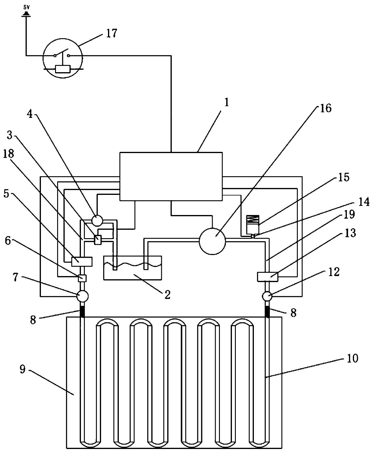
[0020]As shown in the figure, a mold cooling system includes ECU controller 1, water storage cooling tank 2, normally open solenoid valve 3, outlet solenoid valve 5, pressure sensor 6, outlet temperature sensor 7, bellows 8, mold 9, Waterway 10, inlet temperature sensor 12, inlet solenoid valve 13, pressure accumulator pressure sensor 14, pressure accumulator 15, water pump 16, water pipe one 18, water pipe two 19, one end of water pipe one 18 communicates with water storage cooling tank 2 and enters the liquid Below the surface, the other end is in sealing communication with the outlet of the water channel 10. The mold 9 is provided with a water channel 10 in the shape of a coil, and the inlet of the water channel 10 is in sealing communication with one end of the water pipe 19. It is communicated with the water storage cooling tank 2 and submerged below the liquid level. From the water storage cooling tank 2 to the entrance of the waterway 10, the water pipe 2 19 is sequenti...
PUM
Abstract
The invention relates to die stamping technology, in particular to a die cooling system and cleaning method, comprising an ECU controller (1), a water storage cooling tank (2), a normally open electromagnetic valve (3), a cleaning water pump (4), an outlet electromagnetic Valve (5), pressure sensor (6), outlet temperature sensor (7), bellows (8), mold (9), water channel (10), inlet temperature sensor (12), inlet solenoid valve (13), pressure accumulator Pressure sensor (14), pressure accumulator (15), water pump, water pipe one (18), water pipe two, one end of water pipe one (18) communicates with the water storage cooling tank (2) and passes through the normally open solenoid valve (3) It is connected in parallel with the cleaning water pump (4), and the other end communicates with the inlet of the water channel. A water channel in the shape of a coil is arranged in the mold, and the outlet of the water channel communicates with one end of the water pipe two, and the other end of the water pipe two is connected with the water storage The cooling tank is connected, and the first water pipe is connected in series with a pressure accumulator, an inlet solenoid valve and an inlet temperature sensor.
Description
technical field [0001] The invention relates to die stamping technology, in particular to a die cooling system and cleaning method. Background technique [0002] In the prior art, in the hot stamping process of metal products, such as automobile anti-collision beams, since the blank before stamping is heated to a set temperature, it is then placed in a pair of dies of the stamping machine, and the Pressure is applied to plastically deform the blank to obtain the desired shape of the metal product. The strength and strain resistance of stamped metal products are improved. In the stamping production process, due to the high temperature of the blank, the heat exchange with the mold during the continuous production process will cause the temperature of the mold to exceed the normal value, deform the mold and affect the shape of the stamping part, and even directly damage the mold. Therefore, in the existing hot stamping process, a water channel is generally designed in the mol...
Claims
Application Information
Patent Timeline
Application Date:The date an application was filed.
Publication Date:The date a patent or application was officially published.
First Publication Date:The earliest publication date of a patent with the same application number.
Issue Date:Publication date of the patent grant document.
PCT Entry Date:The Entry date of PCT National Phase.
Estimated Expiry Date:The statutory expiry date of a patent right according to the Patent Law, and it is the longest term of protection that the patent right can achieve without the termination of the patent right due to other reasons(Term extension factor has been taken into account ).
Invalid Date:Actual expiry date is based on effective date or publication date of legal transaction data of invalid patent.