Control method and electronic equipment

A control method and technology of powered equipment, applied in the direction of program control design, electrical digital data processing, multi-channel program device, etc., can solve the problems of power board or power adapter power increase and cost increase, etc., and achieve fast speed and increase The effect of high maximum power

Active Publication Date: 2019-07-16
LENOVO (BEIJING) LTD
View PDF6 Cites 1 Cited by
  • Summary
  • Abstract
  • Description
  • Claims
  • Application Information

AI Technical Summary

Problems solved by technology

If you want to increase the maximum power output of the power output interface, you need to increase the design power of the entire electronic device, which will lead to an increase in the power of the power board or power adapter of the electronic device, resulting in an increase in cost

Method used


Image

  • Control method and electronic equipment
  • Control method and electronic equipment
  • Control method and electronic equipment

Examples


Embodiment 1

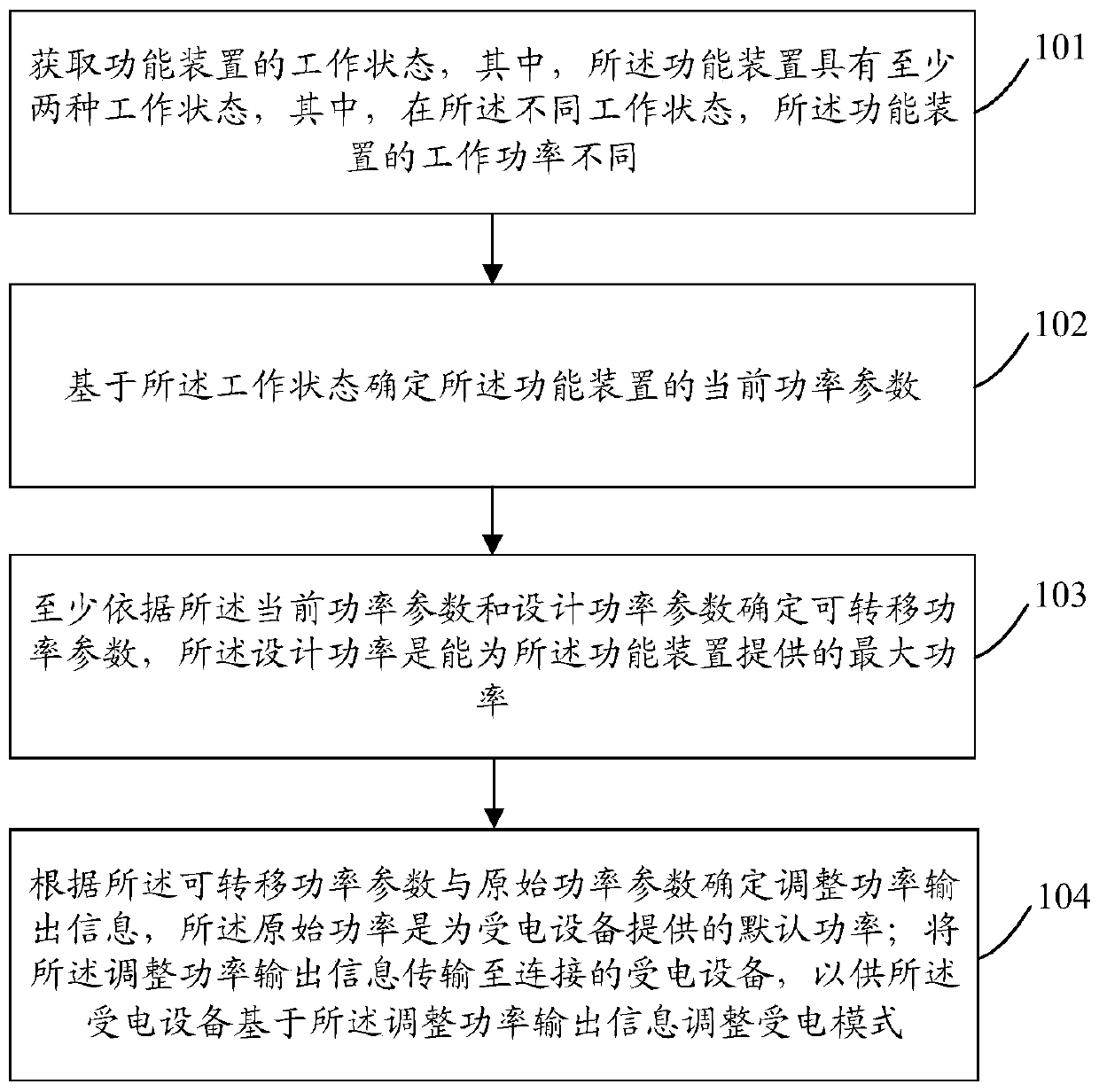
[0054] This embodiment provides a control method, which is applied to electronic equipment, such as figure 1 As shown, the control method mainly includes the following steps:

[0055] Step 101: Obtain the working state of the functional device, wherein the functional device has at least two working states, and the working power of the functional device is different in the different working states.

[0056] That is to say, the functional device is a component with variable power consumption.

[0057] In this embodiment, the functional device may be a component built in the electronic device, or a device connected to the electronic device.

[0058] In this embodiment, the functional devices are at least divided into two categories:

[0059] The first type of functional device only has an on state and an off state;

[0060] The second type of functional device not only has an on state and an off state, but also has different working states corresponding to different target param...

Embodiment 2

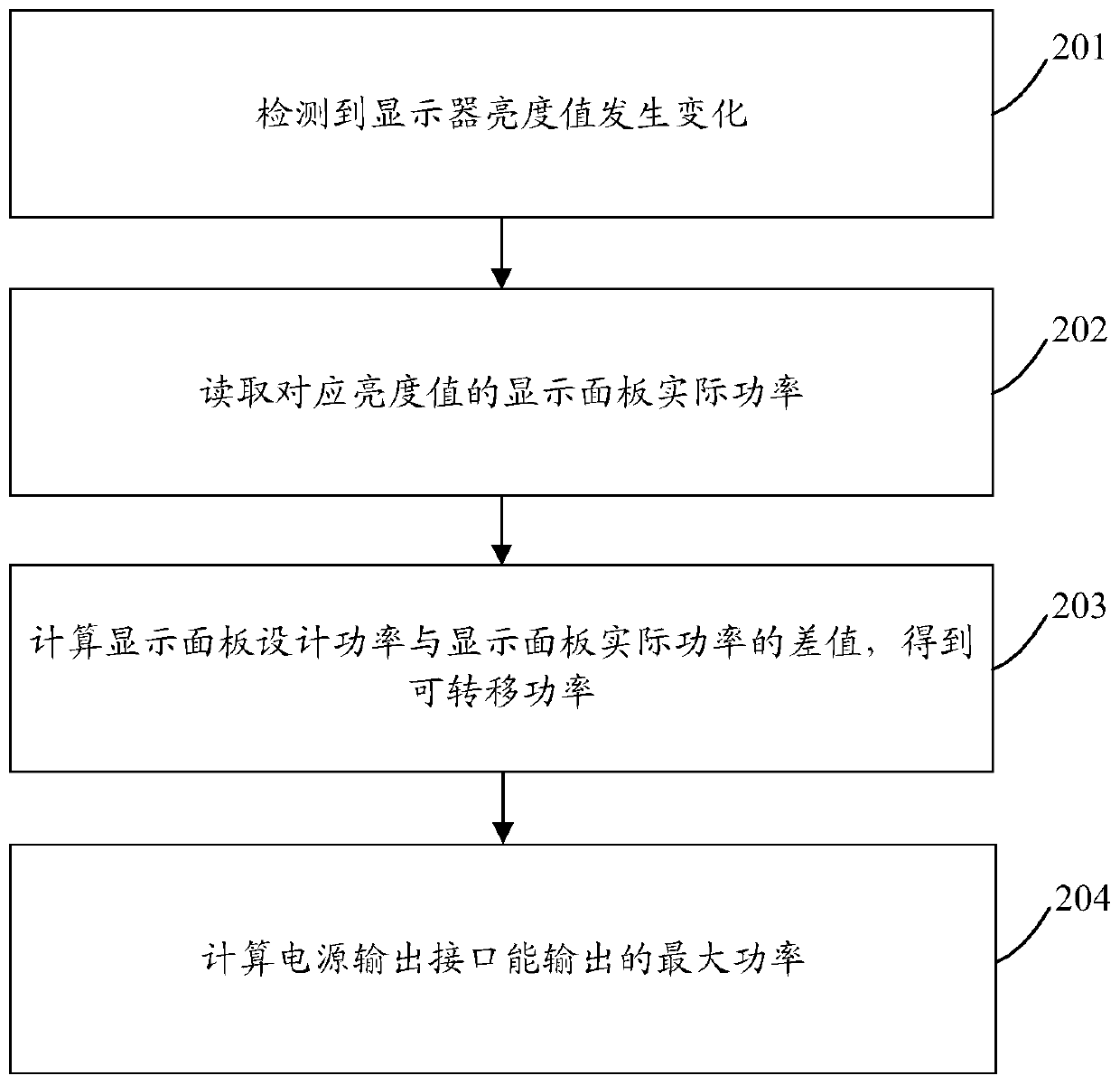
[0116] This embodiment provides a control method, which is applied to electronic equipment, such as figure 2 As shown, the control method mainly includes the following steps:

[0117] Step 201: It is detected that the brightness value of the display changes, and then step 202 is executed.

[0118] Step 202: Read the actual power of the display panel corresponding to the brightness value, and then execute Step 203.

[0119] Step 203: Calculate the difference between the design power of the display panel and the actual power of the display panel to obtain the transferable power, and then perform step 204.

[0120] Wherein, the actual power of the display panel is less than or equal to the design power of the display panel.

[0121] Step 204: Calculate the maximum output power of the power output interface.

[0122] Wherein, the maximum output power of the power output interface is equal to the sum of the default power of the power output interface and the transferable power....

Embodiment 3

[0137] The embodiment of the present application also provides an electronic device, such as Figure 4 As shown, the electronic equipment includes:

[0138] The detection device 10 is used to determine the working state of the representative functional device, determine the current power parameter of the functional device based on the working state, and the functional device has at least two working states, wherein, in the different working states, the The working power of the above functional devices is different;

[0139] The processing device 20 is configured to determine a transferable power parameter based on at least the current power parameter and the design power parameter; determine the adjusted power output information according to the transferable power parameter and the original power parameter, and transmit the adjusted power output information to the powered device, for the powered device to adjust a power receiving mode based on the adjusted power output inform...


PUM


Abstract

The invention discloses a control method and electronic equipment, and the method comprises the steps: obtaining the working state of a functional device, wherein the functional device has at least two working states, and the working power of the functional device is different in the different working states; determining a current power parameter of the functional device based on the working state; determining a transferable power parameter at least according to the current power parameter and a design power parameter, wherein the design power is the maximum power which can be provided for thefunctional device; determining adjusting power output information according to the transferable power parameter and an original power parameter, wherein the original power is default power provided for a powered device; and transmitting the the adjusteing power output information to connected power receiving equipment, so that the power receiving equipment adjusts a power receiving mode based onthe adjusting power output information.

Description

technical field [0001] The present application relates to the field of equipment, in particular to a control method and electronic equipment. Background technique [0002] Currently, for electronic devices that support power output on the market, the maximum power output from the power output interface is constant. If the maximum power output of the power output interface is to be increased, the design power of the entire electronic device must be increased, which will lead to an increase in the power of the power board or power adapter of the electronic device, resulting in an increase in cost. Contents of the invention [0003] In view of this, the technical solution of the present application is achieved in this way: [0004] The embodiment of this application provides a control method, including: [0005] Obtaining the working state of the functional device, wherein the functional device has at least two working states, wherein, in the different working states, the w...

Claims


Application Information

Patent Timeline
Patent Type & Authority Applications(China)
IPC IPC(8): G06F1/3206G06F1/3296G06F9/50
CPCG06F1/3206G06F1/3296G06F9/5038
Inventor 罗雄鹏方伟强崔希波孙宁
Owner LENOVO (BEIJING) LTD
Why Eureka
Try Eureka