

Electrostatic charge storage assembly
a charge storage and electrostatic technology, applied in the field of power supplies, can solve the problems of only providing a limited number of charge-discharge cycles, exposing both the user and the environment to potential injury, and achieving the effect of quick charging
- Summary
- Abstract
- Description
- Claims
- Application Information
AI Technical Summary
Benefits of technology
Problems solved by technology
Method used
Image

Examples
Embodiment Construction
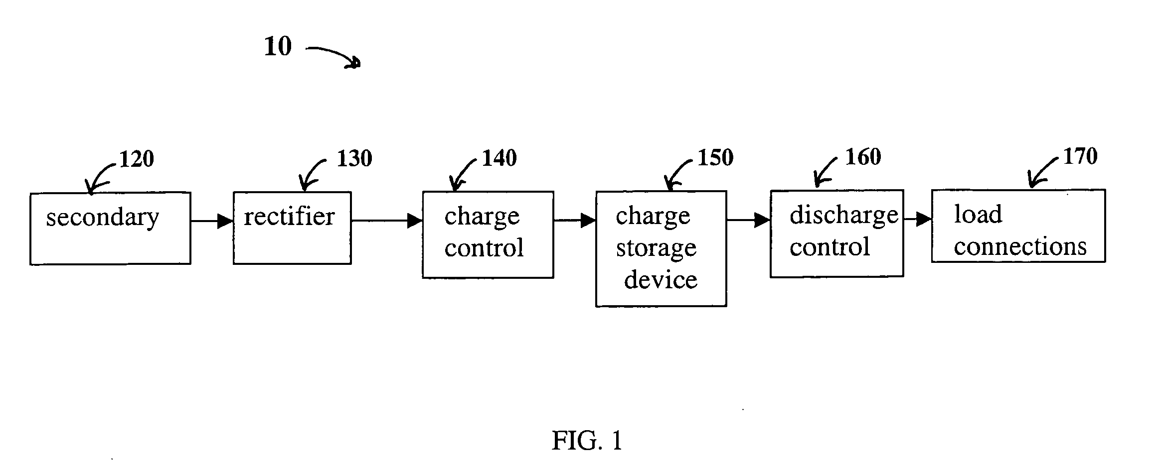
[0027] Referring to FIG. 1, one embodiment of electrostatic charge storage assembly 10 of the present invention includes a secondary 120 which inductively receives an alternating current (AC) signal from the primary (not shown) of a power supply (not shown). Secondary 120 is coupled with rectifier 130. Rectifier 130 is coupled with charge storage device 150 and, optionally, charge control 140. Rectifier 130 converts the AC signal received by secondary 120 to a direct current (DC) signal as described in more detail below. Charge control 140 influences the charging of charge storage device 150 as described in more detail below. Charge storage device 150 is coupled with discharge control 160 and to load connections 170. Discharge control 160 and influences the discharge of charge storage device 150 to a load coupled with load connections 170, as described more fully below. It would be obvious to those skilled in the art that a non-inductive charging system could be used in addition to,...
PUM
| Property | Measurement | Unit |
|---|---|---|
| electrostatic charge | aaaaa | aaaaa |
| electrical charge | aaaaa | aaaaa |
| charge | aaaaa | aaaaa |
Abstract
Description
Claims
Application Information