Exhaust device and tire mold

A technology of exhaust device and exhaust end, which is applied in the direction of tires, household appliances, and other household appliances. It can solve the problems of exhaust hole blockage, easy falling off, and easy cracking, so as to avoid the formation of rubber hair, high stroke accuracy, The effect of not easy to break

Active Publication Date: 2019-12-13
HIMILE MECHANICAL SCI & TECH (SHANDONG) CO LTD
View PDF1 Cites 0 Cited by
  • Summary
  • Abstract
  • Description
  • Claims
  • Application Information

AI Technical Summary

Problems solved by technology

[0005] The exhaust device with the above structure has some problems, for example, the limit part 21' is easily deformed, and the limit part 21' is prone to fatigue damage, and the closing stroke accuracy of the core cap 23' is poor, especially when the elastic force of the spring 3' is limited. Under the action, the closing stroke of the core cap 23` tends to become larger, and the shaft part 2` is not firm enough to fall off easily, the shaft part 2` is easy to deviate from the core, and the rubber is easy to enter the sleeve body 1`, causing the vent hole to be blocked. And then affect the quality of tire vulcanization
On the other hand, the strength of the limiting part 21' is poor, and when the shaft member 2' is disassembled, the root of the limiting part 21' is prone to cracks and breaks.

Method used


Image

  • Exhaust device and tire mold
  • Exhaust device and tire mold
  • Exhaust device and tire mold

Examples


Embodiment 1

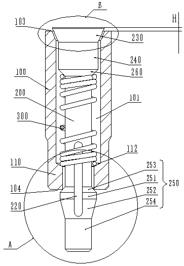
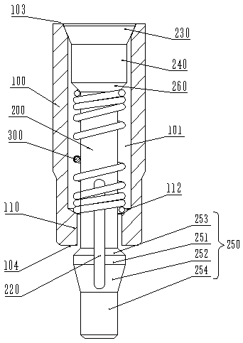
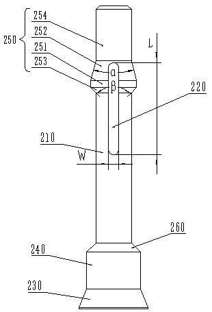
[0052] Such as figure 1 , figure 2 , image 3 with Image 6 As shown, the exhaust device provided by the embodiment of the present invention includes: a mandrel 200 and a casing 100 sheathed on the mandrel 200, an exhaust passage 101 is formed between the casing 100 and the mandrel 200, and the casing 100 has an inlet The gas end 103 and the exhaust end 104; the mandrel 200 includes a shaft body 210, one end of the shaft body 210 is connected to the shaft head 230, and the other end of the shaft body 210 is connected to the shaft end piece 250, and the shaft end piece 250 is provided with a through groove 220, through which The groove 220 runs through the shaft end piece 250, and the end of the through groove 220 away from the shaft head 230 is closed. The shaft end piece 250 is used to limit the axial position of the mandrel 200, and the shaft end piece 250 is also used to shrink and rebound. Matching shell 100 and mandrel 200 . Wherein, the shaft body 210, the shaft he...

Embodiment 2

[0077] Such as Figure 12 , 13 As shown, the difference between this embodiment and Embodiment 1 is that: a guide surface 111 is provided along the outer side of the axially limiting convex ring 110 of the sleeve 100; the guide surface 111 is used to form the exhaust end 104 of the sleeve 100 by An opening of decreasing radial size from outside to inside.

[0078] A step is formed between the first shaft section 251 and the shaft body 210 . When the exhaust device is installed, the outer edge of the first shaft section 251 near the shaft head 230 abuts against the guide surface 111 . When the mandrel 200 is disassembled from the inner cavity of the casing 100 , the shaft end piece 250 slides along the second guide surface 111 , so that the second guide surface 111 guides the shaft end piece 250 . Further, the guide surface 111 can be a conical surface, an inclined surface, an arc surface, etc., preferably a conical surface, and the cone angle θ of the guide surface 111 range...

Embodiment 3

[0081] Such as Figure 14 , 15 As shown, the difference between this embodiment and Embodiments 1 and 2 is that: the shaft end piece 250 is also used to exert a force on the mandrel 200 from the shaft head 230 toward the shaft end piece 250 so that the shaft head 230 abuts against the casing 100 , There is an air intake gap or an air inlet between the shaft head 230 and the casing 100, and the air inlet gap or the air inlet communicates with the exhaust channel 101 and the outside of the exhaust device.


PUM

PropertyMeasurementUnit
angleaaaaaaaaaa
angleaaaaaaaaaa

Abstract

The invention provides an exhaust device and a tire mold, and relates to the technical field of tire vulcanization processing. The exhaust device provided by the present invention includes: a mandrel and a casing sleeved with the mandrel, an exhaust channel is formed between the casing and the mandrel; the mandrel includes a shaft body, one end of the shaft body is connected to the shaft head, and The other end is connected to the shaft end piece, and the shaft end piece is provided with a through groove, and the through groove runs through the shaft end piece, and the end of the through groove away from the shaft head is closed; the shaft end piece is used for axially limiting the shaft body, and the shaft end piece also Used to assemble casings and mandrels by shrinking and springing back. The exhaust device provided by the invention alleviates the technical problems of low closing stroke accuracy of the mandrel, poor firmness of the mandrel, and easy breakage in the prior art, and can avoid the blockage of the exhaust channel and the formation of rubber wool.

Description

technical field [0001] The invention relates to the technical field of tire vulcanization processing, in particular to an exhaust device and a tire mold. Background technique [0002] The current tire production process is roughly as follows: inject fluid or semi-fluid rubber material into the tire mold, and then the rubber material passes through a series of processes in the tire mold to realize tire embryo molding. After the green tire is formed, it is necessary to vulcanize the green tire of the tire. During the vulcanization process, it is necessary to vent the air in the inner cavity of the tire mold. The method usually used at present is to set vent holes on the tire mold, and the air in the tire mold is directly discharged through the vent holes. [0003] However, there are some problems in this way, one of which is that in the process of venting the air out of the tire mold, the rubber material used to form the tire in a fluid or semi-fluid state will also be squee...

Claims


Application Information

Patent Timeline
Patent Type & Authority Patents(China)
IPC IPC(8): B29C33/10B29D30/06
CPCB29D30/0606B29D2030/0617B29C33/10B29D2030/0607
Inventor 张伟王万里杜平孙日文李健冯立新臧贻照
Owner HIMILE MECHANICAL SCI & TECH (SHANDONG) CO LTD
Why Eureka
Try Eureka