Woven fabric

A fabric and fiber technology, applied in the types of packaging items, special packaging items, animal taming devices, etc., can solve the problems of non-disclosure, etc., and achieve the effects of good compression, reduced bending, and good light guide.

Active Publication Date: 2019-07-19
DAIKI CO LTD
View PDF7 Cites 5 Cited by
  • Summary
  • Abstract
  • Description
  • Claims
  • Application Information

AI Technical Summary

Problems solved by technology

[0004] However, in Patent Document 1, it is not disclosed that by designing a complex and highly designed fabric having an optical fiber located on the surface of the fabric and emitting light, and a fixed area hidden on most of the surface without being exposed, etc. It is possible to reduce the bending and pressure of the optical fiber and have a good light-guiding fabric structure or manufacturing method

Method used


Image

  • Woven fabric
  • Woven fabric
  • Woven fabric

Examples


Embodiment approach 1

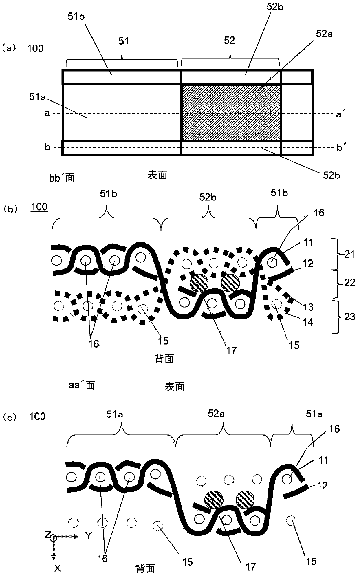
[0117] figure 1 Among them, (a) is a plan view of the fabric 100 of Embodiment 1, (b) is a sectional view of the bb' portion of (a), and (c) is a sectional view of the aa' portion of (a).

[0118]

[0119] Fabric 100 repeats fiber optic region 52 and decorative region 51 . The optical fiber region 52 is a region where the seventh fiber 17 as an optical fiber is braided. The decoration area 51 is an area without optical fibers.

[0120] The fiber region 52 includes a fixed region 52b and a light emitting region 52a. Repeat for both areas. In addition, in order to reduce bending and pressure on the seventh fiber 17 as an optical fiber, the fixed region 52b can make the seventh fiber 17 not exposed on the surface when the seventh fiber 17 as an optical fiber is in a state of excellent light guiding property. It hides fixed regions.

[0121] The fixing region 52b is a region where the seventh fiber 17 is fixed.

[0122] The light emitting region 52a is a region that emits ...

Embodiment approach 2

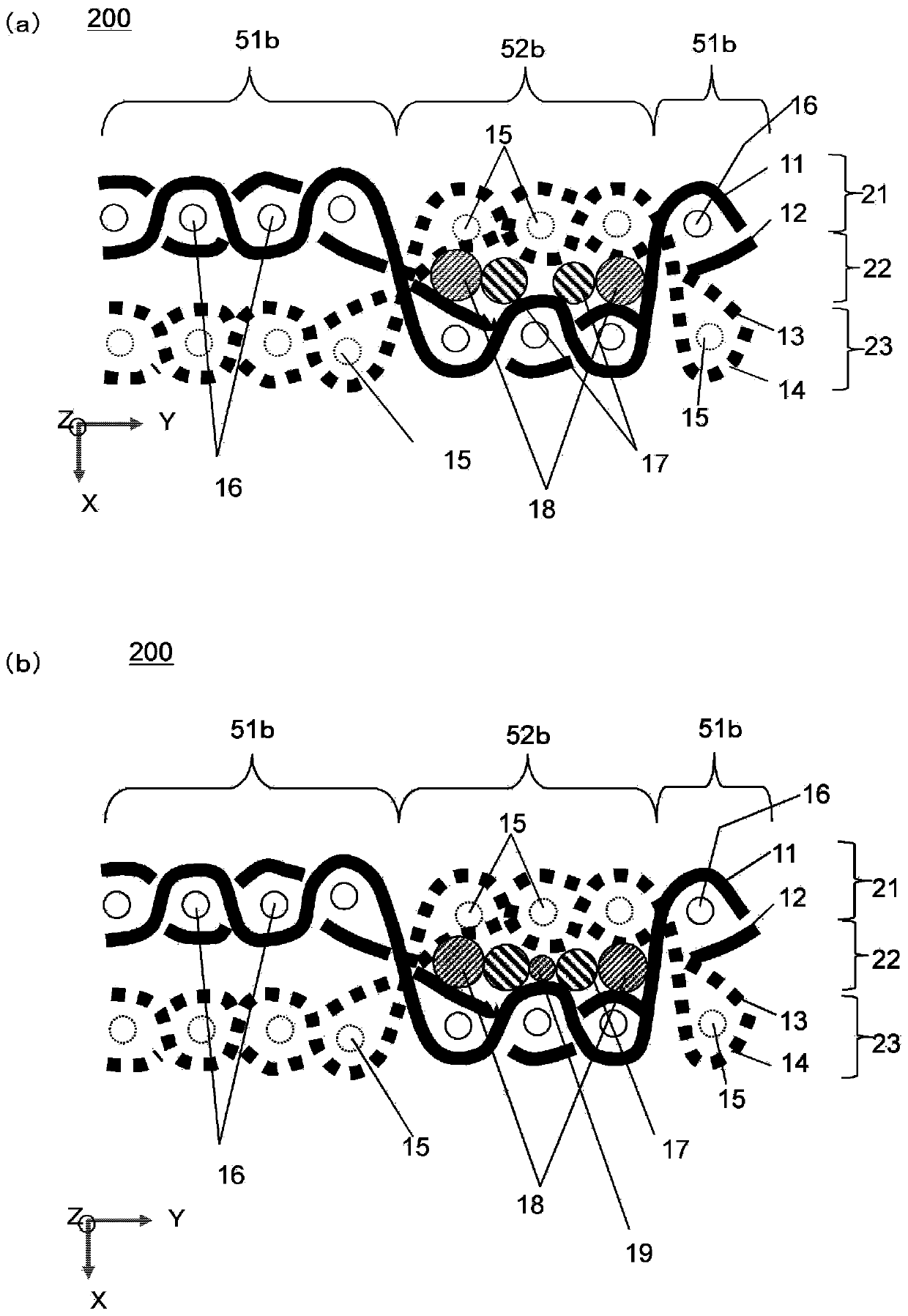
[0168] figure 2 Among them, (a) and (b) are cross-sectional views of the fabric 200 according to the second embodiment. Unlike Embodiment 1, eighth fibers 18 are included. The eighth fiber 18 is a non-optical fiber similarly to the first fiber 11 to sixth fiber 16 . Items not described are the same as those in Embodiment 1. figure 2 (a) and (b) of figure 1 (b), (c) area. Items not described are the same as those in Embodiment 1.

[0169] The seventh fiber 17 (optical fiber) is sandwiched and fixed in the middle layer 22 in the space between the surface layer 21 and the back layer 23 . The eighth fiber 18 is located in the space of the middle layer 22 . The seventh fiber 17 and the eighth fiber 18 are not woven with respect to other fibers, and the seventh fiber 17 (optical fiber) is fixed without hindering linearity. Since the seventh fiber 17 (optical fiber) is not bent, it can emit light efficiently. The eighth fiber 18 also serves to protect the seventh fiber 17 (...

Embodiment approach 3

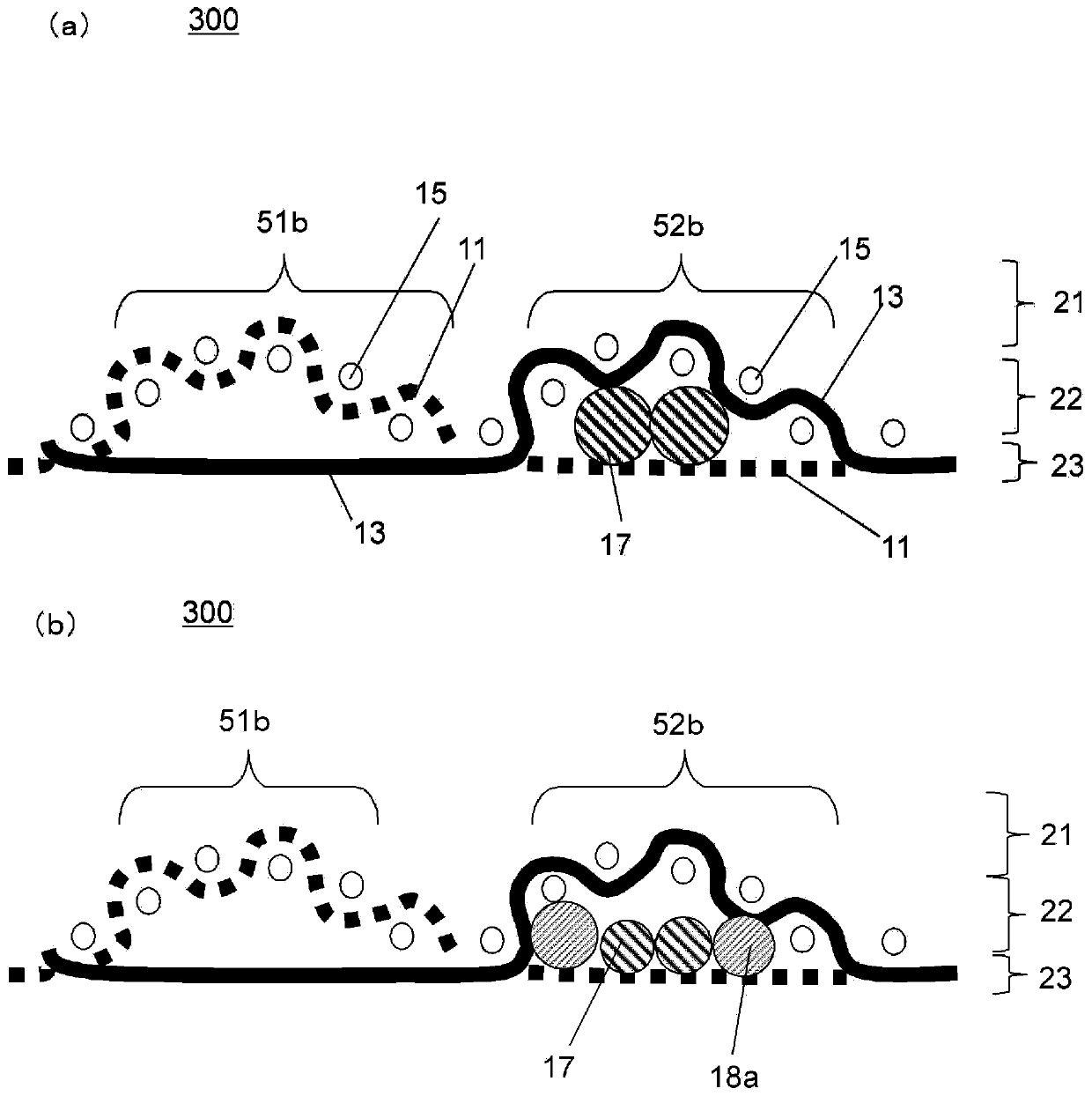
[0179] image 3 Among them, (a) and (b) are cross-sectional views of the fabric 300 according to the third embodiment. Unlike Embodiments 1 and 2, few fibers are used except for the seventh fiber 17 (optical fiber). Items not described are the same as those in Embodiments 1 and 2.

[0180] image 3 Among them, (a) and (b) represent regions corresponding to the fixed region 52b and the second decorative region 51b in the first embodiment.

[0181] In the fixing region 52b, the fifth fiber 15 and the third fiber 13 are woven, and the first fiber 11 is not woven. In the region of the middle layer 22 between the surface layer 21 where the fifth fiber 15 and the third fiber 13 are braided and the first fiber 11 (back layer 23 ), the optical fiber of the seventh fiber 17 is arranged. The region of the intermediate layer 22 is connected in a straight line, and the straightness of the optical fiber of the seventh fiber 17 can be ensured. As a result, the optical fiber can be fixe...


PUM


Abstract

The invention provides a woven fabric, a lighting device, a curtain, a stair lighting device, a bag, a speaker device, a monitor, a collar, a shoe, and a portable terminal. Through the design, in a complicated and highly designed woven fabric having a region where the optical fiber is located on the surface of the woven fabric and emits light, and a fixed region hidden in the surface where the surface is barely exposed, the bending and pressing of the optical fiber can be minimized, and the optical guiding performance is high. The woven fabric includes: a fixing region where an optical fiber of a seventh fiber is held, and a light emitting region where the optical fiber of the seventh fiber is included to emit light. The woven fabric includes: a back layer in which a first fiber, a secondfiber, and a sixth fiber are woven; a surface layer in which a third fiber, a fourth fiber, and a fifth fiber are woven; and the optical fiber arranged in a space of an intermediate layer between thesurface layer and the back layer.

Description

technical field [0001] This invention relates to fabrics. In particular, it relates to a fabric in which an optical fiber or a cylindrical body is inserted into a part of the fabric. Background technique [0002] In the prior art, fabrics in which optical fibers are embedded in a portion of the fabric have been considered. For example, Patent Document 1 discloses a fabric in which an optical fiber is embedded in a part of the fabric. [0003] [Patent Document 1] Japanese Unexamined Patent Publication No. 2009-84738 [0004] However, in Patent Document 1, it is not disclosed that by designing a complex and highly designed fabric having an optical fiber located on the surface of the fabric and emitting light, and a fixed area hidden on most of the surface without being exposed, etc. It is possible to reduce the bending and pressure of the optical fiber and have a good light-guiding fabric structure or manufacturing method. Contents of the invention [0005] The present i...

Claims


Application Information

Patent Timeline
Patent Type & Authority Applications(China)
IPC IPC(8): B32B27/02B32B27/12B32B27/18B32B27/20B32B27/30B32B27/32B32B27/34B32B27/36B32B5/14A01K27/00F21V8/00F21V33/00H04R1/02A47H23/08A45C13/08A45C13/00A43B3/00A43B23/02
CPCB32B5/024B32B5/08B32B5/142B32B5/26A01K27/001A01K27/006F21V33/0008F21V33/0056F21V33/00H04R1/028A47H23/08A45C13/08A45C13/00A43B23/0245B32B2250/20B32B2262/0246B32B2262/0253B32B2262/0261B32B2262/0284B32B2262/12B32B2262/14B32B2437/02B32B2439/00F21V2200/10F21Y2115/10A47H2023/006A43B3/36
Inventor 山本岳由池田顺治
Owner DAIKI CO LTD
Why Eureka
Try Eureka