Ice breaking ship

An icebreaker and hull technology, applied in icebreakers, special purpose ships, ships, etc., can solve the problems of not too high ice breaking efficiency, damage to the hull structure, low ice breaking efficiency, etc. effect of force

Pending Publication Date: 2019-07-19
JIANGSU UNIV OF SCI & TECH
View PDF0 Cites 5 Cited by
  • Summary
  • Abstract
  • Description
  • Claims
  • Application Information

AI Technical Summary

Problems solved by technology

However, the ice-breaking efficiency is not too high. When encountering an overly thick ice layer, one collision will not break the ice ...

Method used


Image

  • Ice breaking ship
  • Ice breaking ship
  • Ice breaking ship

Examples


Embodiment 1

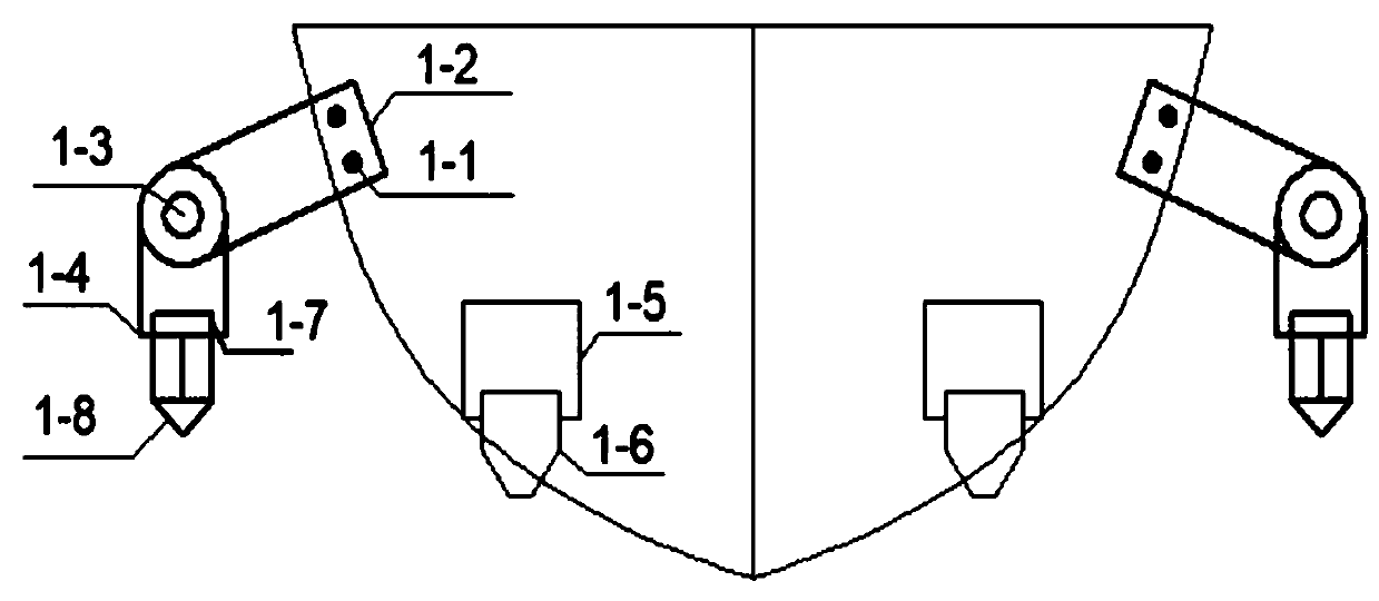
[0042] Through the second hydraulic device 1-5, the lengths of the four circular table structures 1-6 protruding from the bottom of the ship are consistent, that is, the four circular table structures 1-6 are located on the same level, because the second hydraulic device 1-5 It is a three-stage type, and the second hydraulic device 1-5 contracts up and down at the same speed. At this time, the contact area between the icebreaker and the ice surface is reduced, and the force of the unit contact surface is increased, and through the up and down contraction, the potential energy is used Effect, speed up the efficiency of ice breaking.

Embodiment 2

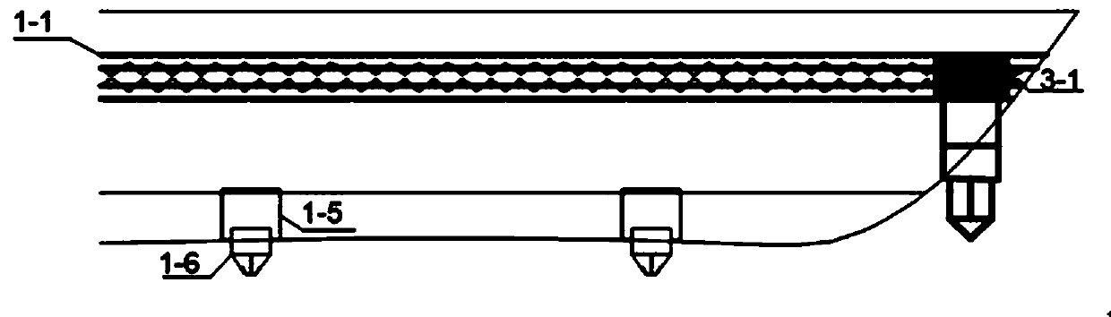
[0044] Through the second hydraulic device 1-5, since the second hydraulic device 1-5 is a three-stage type, the protruding length of the round table structure 1-6 of the bow from the bottom of the ship can be smaller than the length of the round table structure 1-6 of the stern. 6 length protruding from the bottom of the ship, so the gravity of the hull is concentrated on the stern part, thereby increasing the force of the ice layer at the stern by the circular platform structure 1-6, and increasing the ice-breaking efficiency.

Embodiment 3

[0046] Through the second hydraulic device 1-5, since the second hydraulic device 1-5 is a three-stage type, the length of the protruding circular platform structure 1-6 from the left side of the bottom of the ship is smaller than that of the stern circular platform structure 1 -6 length protruding from the right side of the bottom of the ship, the gravity of the hull is concentrated on the right part of the bottom of the ship, thereby increasing the force of the ice layer at the stern by the circular platform structure 1-6, and increasing the ice-breaking efficiency.

[0047] As can be seen from the above three embodiments, by adjusting the length of the round platform structure 1-6 from the bottom of the ship through 4 adjustments, the gravity of the ship can be concentrated on the front or rear or left or right of the ship, through the round platform structure 1 The up and down contraction movement of -6 uses the principle of gravitational potential energy to assist the ice ...


PUM


Abstract

The invention provides an ice breaking ship. Continuous method ice breaking devices are correspondingly arranged on the broadsides on the two sides of a ship body, an impact method ice breaking deviceis arranged at the bottom of the ship body, according to the ice breaking ship, the continuous method ice breaking devices are provided, before the ice breaking ship is contacted with an ice layer, the action of a cone head structure on a hydraulic device is used for providing an instantaneous impact force for the vertical cross section of the ice layer, multiple times of impact can be achieved and used for breaking the inner part structure of the ice layer, crushability of the ice layer can be increased, and thus resistance is reduced in continuous ice breaking; and the action can also be used for breaking floating ice on the two sides of the ice breaking ship during sailing, thus lateral pressure on the ship body broadsides from the floating ice is reduced, and wear-out failure is reduced. According to the ice breaking ship, the impact method ice breaking device is provided, the ice breaking device extending out of the bottom of the ship and the potential energy effect are used, theice breaking efficiency is increased, the gravity of the ship bottom can be used for being gathered at one point or a part, thus stress of the ice layer is increased, the ice breaking efficiency is increased, and meanwhile the ship body structure is not damaged.

Description

technical field [0001] The invention belongs to the technical field of shipbuilding, in particular to an icebreaker. Background technique [0002] In 1864, the Russians refitted a small ship "Pirot" into the world's first icebreaker to keep the route from Kronstadt to Oranienbaum open during the frozen period. The Russian-built "Yermak" icebreaker was the first icebreaker to sail in the Arctic. Since the 19th century, icebreakers have been continuously developed. Icebreakers are service ships used to break the ice on the water surface, open up waterways, ensure ships enter and exit ice-covered ports and anchorages, or guide ships to navigate in ice areas. Most European and American countries are located in extremely cold regions, and the rivers have been frozen for a long time, which is not conducive to the travel of ships. Therefore, these countries attach great importance to the development of icebreaker technology. On the other hand, with the development of science an...

Claims


Application Information

Patent Timeline
IPC IPC(8): B63B35/08B63B35/12
CPCB63B35/083B63B35/12
Inventor 周利丁仕风沈中祥朱亚洲韩月高俊亮宋明
Owner JIANGSU UNIV OF SCI & TECH
Why Eureka
Try Eureka