
Blade cutting device and containment testing device for aero-engine fan case

A technology of cutting device and test device, which is applied in the direction of engine testing, engine starting, engine components, etc., can solve the problems of affecting test results, affecting efficiency, and large errors, so as to ensure safe operation, reliable installation, and avoid stress concentration Effect

Active Publication Date: 2019-07-19
AECC SHENYANG ENGINE RES INST
View PDF9 Cites 4 Cited by
  • Summary
  • Abstract
  • Description
  • Claims
  • Application Information

AI Technical Summary

Problems solved by technology

[0006] Due to the influence of material dispersion, processing error and notch sensitivity, the prefabricated notch method has low control accuracy of the fly-off speed. In practical applications, conservative prefabricated notches are usually used, resulting in the need to go up and down the test many times, and the success rate of the test is difficult. ensure
[0007] The method of combining prefabricated gaps and local rapid heating is only suitable for metal materials whose tensile strength is sensitive to temperature rise. In addition, it also faces the problem of difficult wiring when applied in component level and complete machine containment tests.
[0008] Using contact blasting to break the blade, because the detonation pressure has no directionality, it will increase the extra kinetic energy of the blade flying outward, thus affecting the test results; the energy-concentrating cutter is external, and it is at the tenon fracture position required by the actual engine containment test There is not enough layout space, and it cannot be directly applied to the engine component level and the complete machine containment test
[0009] 2. Cost
[0012] The existing fly-off speed control technology has large errors, and repeated tests are required, which affects efficiency

Method used


Image

  • Blade cutting device and containment testing device for aero-engine fan case
  • Blade cutting device and containment testing device for aero-engine fan case
  • Blade cutting device and containment testing device for aero-engine fan case

Examples


no. 1 example

[0073] Such as Figure 8 As shown, in this embodiment, the containment test device of the present application may also include a journal 78 and a conductive slip ring 79 . The journal 78 is fixedly arranged in the test cavity 72, and is sleeved on the top of the transfer section 74 outside the drive shaft 73, and will not rotate with the drive shaft 73; the conductive slip ring 79 is coaxially sleeved on the outside of the journal 78, and passes through The lead that runs through the vacuum chamber cover 71 is connected with the detonation switch.

[0074] Further, the detonating power supply line 6 of the blade cutting device is fixedly laid along the tenon 101 of the blade 10 to be cut, the fan disc 77 and the surface of the transition section 74; more specifically, the detonating power supply connected to the detonator 5 at the upper end of the charging hole 1 Line 6 is formed by tenon 101 upper surface, fan disk 77 rear end surfaces ( Figure 8 middle and upper surface),...

no. 2 example

[0077] The difference from the first embodiment above is that in this embodiment, the slip ring lead 81 is arranged outside the test chamber 72; the slip ring lead 81 is sleeved on the drive shaft outside the test chamber 72 through the lead mount 82 73, and be connected with detonation switch by lead; Further, there is inner hole at drive shaft 73 centers.

[0078] After the detonating power line 6 connected to the detonator 5 at the upper and lower ends of the charging hole 1 is led out to the transition section 74, it penetrates into the interior of the transition section 74 at the top of the transition section 74, and extends from the inner hole at the bottom of the drive shaft 73. It is connected to the slip ring lead 81, so that the detonating switch can detonate the detonator 5 smoothly.

no. 3 example

[0080] In this embodiment, the containment test device may further include a power box 91 and a wireless signal transmitting device 92 .

[0081] Wherein, the power supply box 91 is fixedly arranged on the inner wall of the transition section 74, and the inside of the power supply box 91 may include a power supply, a wireless control switch and a wireless signal receiving device. The wireless control switch is used to control the power on and off; the wireless signal receiving device is used to receive the wireless control signal, and control the wireless control switch according to the wireless control signal.

[0082] Wherein, the detonating power cord 6 connected to the detonator 5 at the upper and lower ends of the charging hole 1 is led out to the transition section 74 in the same way as the above two embodiments. After being drawn out to the transition section 74, the detonating power cord 6 runs through Extend into the inside of the transition section 74 and connect wit...


PUM


Abstract

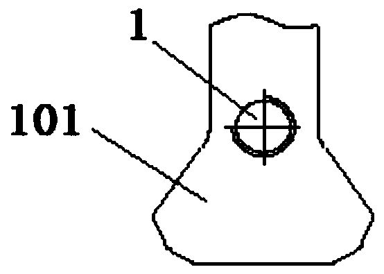
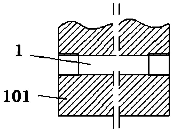
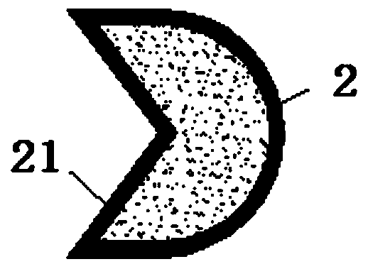
The invention belongs to the field of aero-engine fan case containment testing, and particularly relates to a blade cutting device and a containment testing device for an aero-engine fan case. The blade cutting device comprises a charging hole, a cutting cable, plastic steel mud, a detonator fixing bolt and a detonating switch, wherein the charging hole is formed in a to-be-cut blade tenon, and the two ends of the charging hole are provided with internal threads; the cutting cable is laid in the charging hole; the plastic steel mud is arranged in the gap between the cutting cable and the charging hole; the detonator fixing bolt is installed at the bottom of one end of the charging hole through a thread and internally provided with a detonator, and two detonator leads of the detonator stretch out of the top of the detonator fixing bolt through a lead passing hole; and the detonating switch is connected with the detonator leads through two detonating power lines so that the detonator canbe ignited. According to the blade cutting device and the containment testing device, a blade can be cut off at the specific rotation speed, so that the testing result is real and effective, in addition, large stress concentration can be avoided, the detonator and the cutting cable can be installed finally, the operation safety of testing piece assembling and lead working is ensured, and it can be ensured that a detonating system operates safely and reliably.

Description

technical field [0001] The application belongs to the field of containment test of aero-engine fan case, and in particular relates to a blade cutting device and a containment test device for aero-engine fan case. Background technique [0002] In the case of gas turbine engines, the high-energy debris generated when rotating parts fail puts the engine itself, the aircraft, control surfaces, fuel tanks and pilots at risk. Once the engine is not contained, the aircraft will be damaged, ranging from the loss of flight function to the loss of flight function, and the crash of the aircraft. Therefore, military and civilian gas turbine engine specifications worldwide all have inclusive relevant requirements without exception. The content is basically the same. At least 80% of a single blade must be damaged and contained, and the resulting engine damage must not have any dangerous effect on the aircraft. Generally, engine specifications require verification of fan blade containmen...

Claims


Application Information

Patent Timeline
Patent Type & Authority Applications(China)
IPC IPC(8): F01D21/00F01D25/00F01D19/00G01M15/02
CPCF01D19/00F01D21/003F01D25/00G01M15/02
Inventor 陈国栋姜晓斌王海舟祝昭丹王彤辉张昕东卢序田昊刘正峰赵诗杨
Owner AECC SHENYANG ENGINE RES INST
Learn More