Detecting mechanism for rotor embedding grooves of large-medium high-voltage motors

A high-voltage motor and rotor slot technology, applied in the direction of angle/taper measurement, etc., can solve the problems of copper strip tension falling off, difficulty in ensuring accuracy, and workpiece scrapping, etc., to improve work efficiency, ensure success rate, and reduce labor intensity. Effect

Pending Publication Date: 2019-07-19
黑龙江齐四机床有限公司
View PDF0 Cites 2 Cited by
  • Summary
  • Abstract
  • Description
  • Claims
  • Application Information

AI Technical Summary

Problems solved by technology

Due to the large size of the high-voltage motor rotor, there are many rotor slots, and the distance between the rotor slots is extremely small, many high-voltage motor rotor workpieces that need to be pressed by copper bars cannot be processed directly from the drawings. If the parameters of the workpiece drawings are used directly Input the copper bars into the machine tool for embedding. When there is a deviation between the ends of the rotor slots, the rolling knife will easily distort the V-shaped indentation of the copper bars, causing the copper bars to fall off due to insufficient tension, and even the rotor of the motor. The outer wall is crushed, resulting in the scrapping of the entire workpiece, while manual inspection can only be measured manually through tools, which is not only very laborious to inspect, but also difficult to guarantee accurate results

Method used


Image

  • Detecting mechanism for rotor embedding grooves of large-medium high-voltage motors
  • Detecting mechanism for rotor embedding grooves of large-medium high-voltage motors
  • Detecting mechanism for rotor embedding grooves of large-medium high-voltage motors

Examples


Embodiment Construction

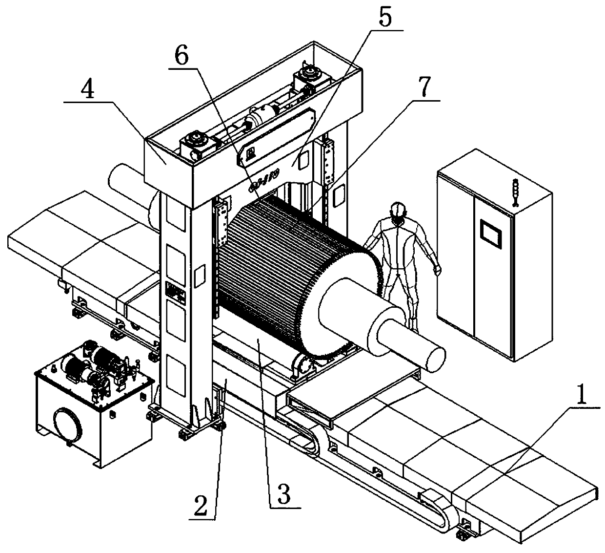
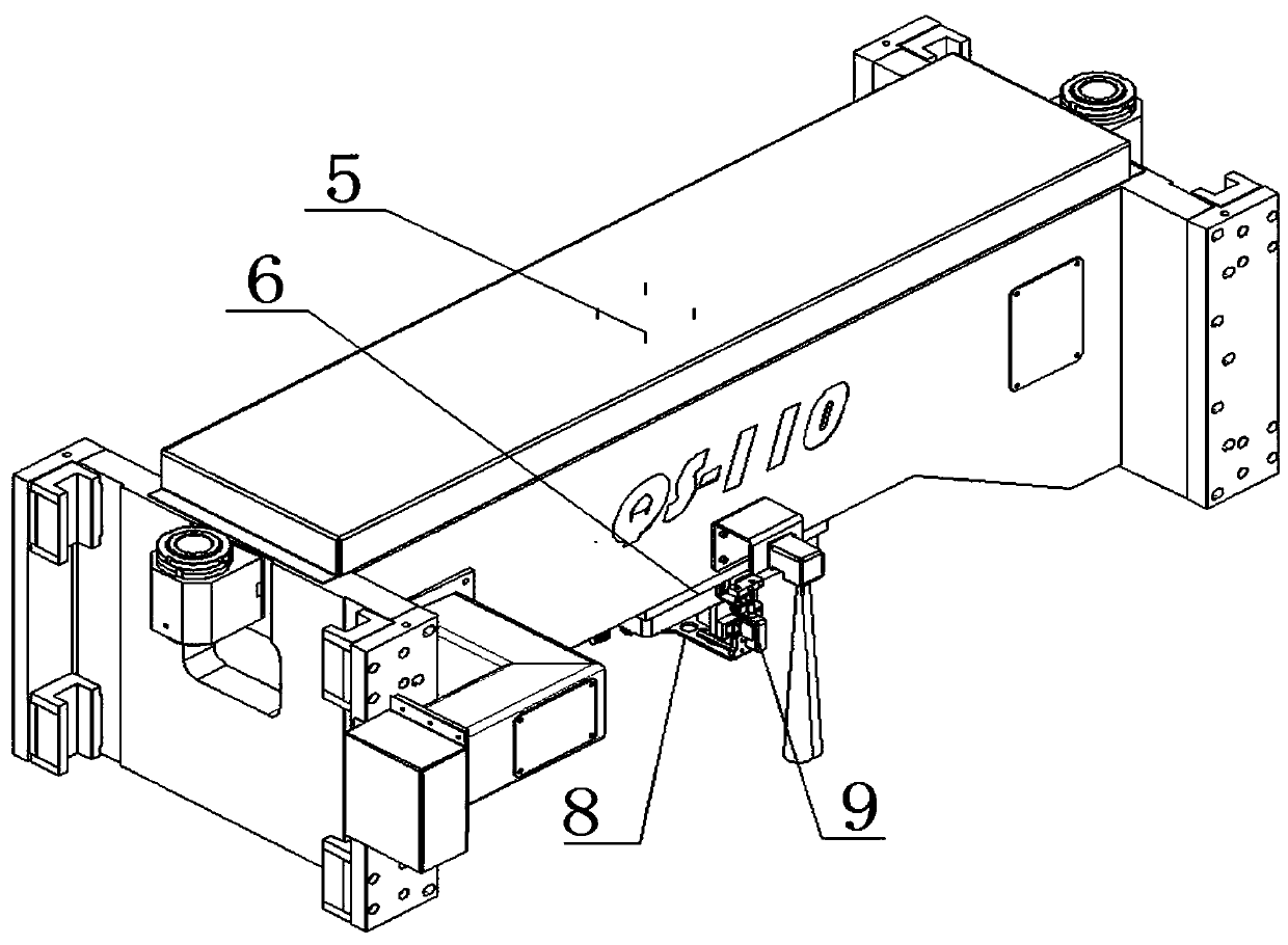
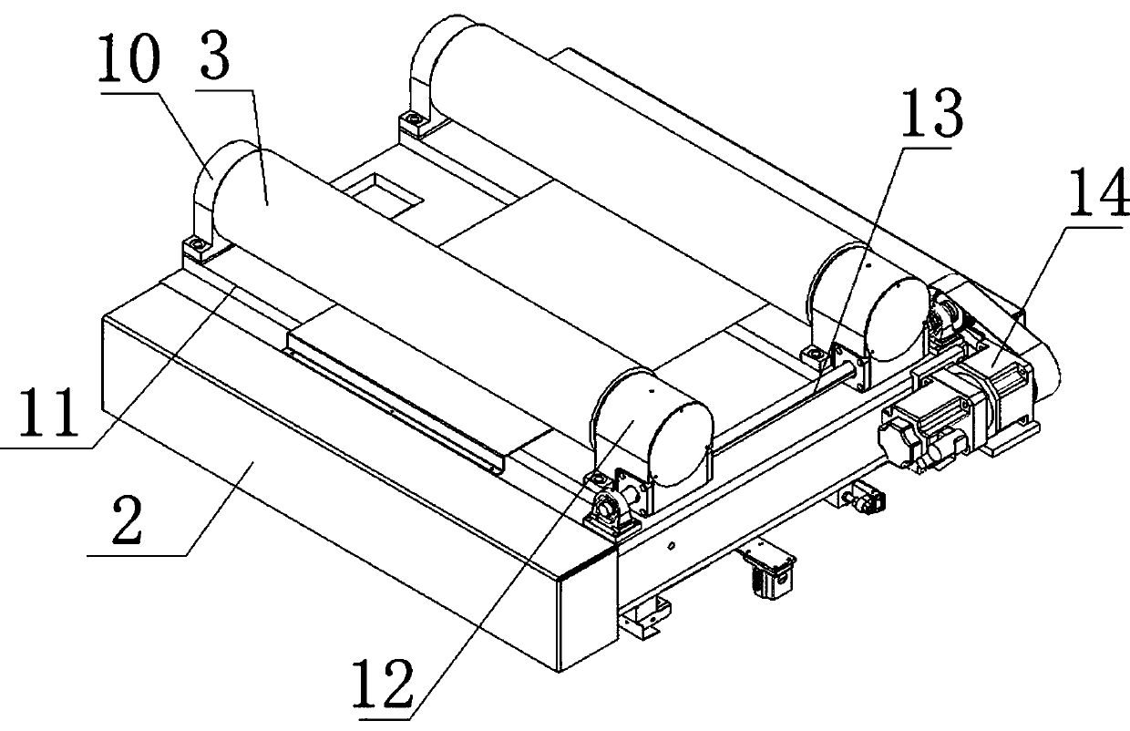
[0022] Such as Figure 1-7 As shown, a large and medium-sized high-voltage motor rotor embedding groove detection mechanism, the high-voltage motor rotor copper bar embedded tight rolling machine bed 1 is provided with a sliding table mechanism 2 capable of horizontal displacement, above the sliding table mechanism 2 is provided The sliding plate 11 driven by the motor can adjust the spacing. The sliding plate 11 is provided with a rotatable driving drum 3, and the two driving drums 3 support the high-voltage motor rotor 7. The ends of the two driving drums 3 are equipped with worm and worm mechanisms. The worm mechanism 12 is connected through a light rod 13, and the light rod 13 is connected with the gear reducer 14, and the gear reducer 14 controls the synchronous operation of the two drive rollers 3 through the light rod 13, so that the high-voltage motor rotor 7 above it realizes indexing operation, and the A gantry 4 is arranged above the sliding table mechanism 2, and i...


PUM


Abstract

The invention discloses a detecting mechanism for rotor embedding grooves of large-medium high-voltage motors, and belongs to the technical field of electrical equipment special for numerical control.The detecting mechanism is arranged on a cross beam and comprises a rotor groove end-to-end inclination detection device and a detection device for angles between the rotor grooves; the rotor grooveend-to-end inclination detection device comprises a main inclination detection device and an auxiliary inclination detection device, the main inclination detection device is positioned in front of a hydraulic oil cylinder of the cross beam, the auxiliary inclination detection device is located beside the main inclination detection device on the cross beam, the main inclination detection device isused for detecting the uppermost rotor groove at the axis of a high-voltage motor rotor, and the auxiliary inclination detection device is used for detecting the rotor grooves on one side. The detection device for the angles between the rotor grooves is composed of a displacement sensor, a check block, a vertical plate and an L-shaped frame plate, and the displacement sensor is used for enabling pulse numerical values of detection rollers to be displayed by a display screen through a PLC. According to the detecting mechanism, whether the rotor grooves of the high-voltage motor rotor are inclined or not can be detected, and whether the indexing of a workpiece is accurate or not can be detected.

Description

technical field [0001] The invention relates to a large and medium-sized high-voltage motor rotor embedding groove detection mechanism, which belongs to the technical field of numerical control special electrical equipment. Background technique [0002] Large-scale high-voltage motors require that the rotor copper strips be mechanically embedded to ensure that the motor provides continuous and stable power. The large and medium-sized high-voltage motor rotor copper strip rolling machines are used to insert the copper strips so that the rolling knives can be rolled and extruded in a straight line along the axial direction. The method is to make V-shaped indentation on the outer surface of the copper bar, and to fix it with the rotor groove through local plastic deformation of the copper bar, which is the most efficient processing method at present. Due to the large size of the high-voltage motor rotor, there are many rotor slots, and the distance between the rotor slots is ex...

Claims


Application Information

Patent Timeline
IPC IPC(8): G01B5/25
CPCG01B5/25
Inventor 徐彦东牟忠凯吴美萱
Owner 黑龙江齐四机床有限公司
Why Eureka
Try Eureka