Wire winding ring jack contact element and wire winding ring jack

A socket contact and wire winding technology, which is applied to the parts, connections, electrical components, etc. of the connection device, to achieve the effects of easy installation, lower temperature rise, and optimized internal structure

Pending Publication Date: 2019-07-19
刘育娥
View PDF0 Cites 0 Cited by
  • Summary
  • Abstract
  • Description
  • Claims
  • Application Information

AI Technical Summary

Problems solved by technology

[0003] However, the performance of grid copper wi

Method used


Image

  • Wire winding ring jack contact element and wire winding ring jack
  • Wire winding ring jack contact element and wire winding ring jack
  • Wire winding ring jack contact element and wire winding ring jack

Examples


Example Embodiment

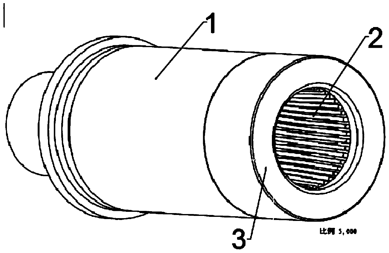
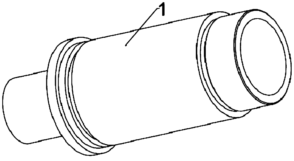
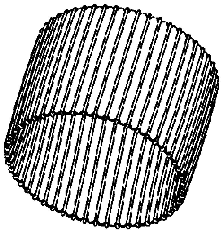
[0015] Example 1, such as Figure 1 to Figure 3 Shown:

[0016] A wire-wound ring socket contact and a wire-wound ring socket, including a metal copper sleeve 1, a wire-wound spring 2, and a metal gland 3. The wire-wrapped spring 2 is initially in the shape of a strip and rolled into a circle when assembled. Set in 1 hole of metal copper sleeve.

[0017] A preferred technical solution of this embodiment, the coiled wire spring 2 is made of strip-shaped beryllium copper wire or pure copper wire, with a strip-shaped shrapnel as the core, and when viewed from the width direction, the middle strip-shaped shrapnel is the center line. The copper wires are convex in different sizes.

[0018] A preferred technical solution of the present embodiment, it adjusts the spacing p of the wire spring 2 and the diameter of the copper wire Increase its current-carrying size and temperature.


PUM


Abstract

The invention discloses a wire winding ring jack contact element and a wire winding ring jack, comprising a metal copper sleeve, a wire winding spring and a metal gland, wherein the initial state of the wire winding spring is in a strip shape, and the wire winding spring is arranged in the metal copper sleeve hole in a circular shape during assembly. The invention is beneficial to subsequent maintenance and use, and the wire winding spring is more convenient to wind; meanwhile, the distance p between the winding wires and the diameter of the copper wire can be adjusted to improve the current carrying size thereof, so that the temperature rise is reduced, and the overall performance is improved.

Description

technical field [0001] The invention relates to the technical field of electrical connectors, in particular to a wire-wrapped ring socket contact and a wire-wrapped ring socket. Background technique [0002] The full name of the hyperboloid wire spring jack is a single-leaf rotary hyperboloid wire spring jack, which is a highly reliable jack component used in electrical connector (ie connector) products. A plurality of elastic gold-plated or silver-plated metal wires are arranged in the hole according to the straight generatrix of the single-leaf rotary hyperboloid, and form an included angle with the straight generatrix of the inner sleeve. When the pin is inserted into the wire spring hole, the wire spring wire is elastically deformed in the radial and axial directions, and the pin is in contact with multiple independent wire spring wires in the wire spring hole at the same time, forming multiple independent current paths. Even if individual wire spring wires in the jack ...

Claims


Application Information

Patent Timeline
IPC IPC(8): H01R13/187
CPCH01R13/187
Inventor 刘育娥
Owner 刘育娥
Why Eureka
Try Eureka