

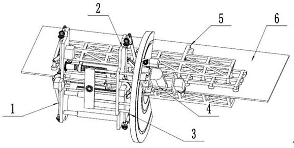
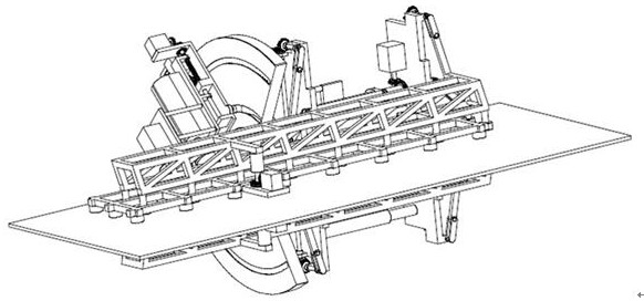
A mobile chamfering robot attached to a steel plate
A robot and chamfering technology, which is applied in the direction of grinding drive devices, grinding machine parts, machine tools suitable for grinding the edge of workpieces, etc., can solve the problems of not being suitable for large steel plate chamfering, time-consuming and labor-intensive, etc.
- Summary
- Abstract
- Description
- Claims
- Application Information
AI Technical Summary
Problems solved by technology
Method used
Image

Examples
Embodiment Construction
[0019] The present invention will be further described below in conjunction with specific embodiments. The exemplary embodiments and descriptions of the present invention are used to explain the present invention, but not as a limitation to the present invention.
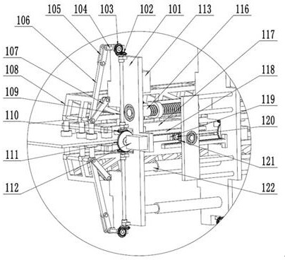
[0020] Such as figure 1 , figure 2 , image 3 , Figure 4 , Figure 5 , Figure 6In the mobile chamfering robot attached to the steel plate shown, the second rotating shaft 109 of the leg of the mechanism 1 before walking has two symmetrical rotations installed on the supporting plate 101 of the mechanism before walking, and the third bevel gear 110 of the leg is fixedly installed At one end of the second rotating shaft 109 of the leg, and form a gear fit with the fourth bevel gear 111 of the leg, the fourth bevel gear 111 of the leg is fixedly installed on the rotating shaft of the leg motor 112, and the leg motor 112 is fixedly installed on the walking shaft On the front mechanism support plate 101, the firs...
PUM
 Abstract
Description
Claims
Application Information