
A fully automatic wood chamfering device

A chamfering device, fully automatic technology, applied in the direction of grinding drive device, grinding feed movement, manufacturing tools, etc., can solve the problems of difficult to control accuracy, time-consuming, laborious, troublesome, etc.

Active Publication Date: 2021-06-25
叶宇婷
View PDF10 Cites 0 Cited by
  • Summary
  • Abstract
  • Description
  • Claims
  • Application Information

AI Technical Summary

Problems solved by technology

[0002] In the prior art, the technological process of chamfering wood boards usually uses workers to work with hand-held electric planers, manual operation of automatic chamfering machines, and traditional manual tools for cutting and processing. The above-mentioned methods have the following wall ends: workers hold The operation of the electric planer is difficult, and it is difficult to control the accuracy. The manual operation of the automatic chamfering machine requires the worker to hold the wooden board to perform each chamfering and at the same time operate various instructions, which is cumbersome; using traditional tools to perform it Cutting is time-consuming and difficult to maintain accuracy

Method used


Image

  • A fully automatic wood chamfering device
  • A fully automatic wood chamfering device
  • A fully automatic wood chamfering device

Examples


Embodiment Construction

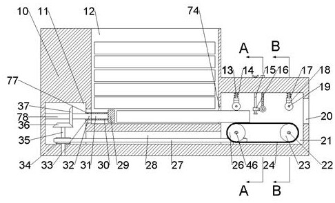
[0017] Combine below Figure 1-6 The present invention is described in detail, wherein, for the convenience of description, the orientations mentioned below are defined as follows: figure 1 The up, down, left, right, front and back directions of the projection relationship itself are the same.

[0018] A full-automatic wood chamfering device described in conjunction with accompanying drawings 1-6 includes a main box body 10, a pushing working cavity 11 is arranged inside the main box body 10, and a pushing working cavity 11 is arranged on the right side of the pushing working cavity 11. Block storage cavity 33, the right side of the push block storage cavity 33 is connected with a plate placement cavity 12, and the lower side of the push block storage cavity 33 is provided with a belt drive cavity 28 communicated with the push working cavity 11, the plate The right side of the placement chamber 12 is communicated with a turning limit chamber 74, and the right side of the stee...


PUM


Abstract

The invention relates to the related field of wood processing, and discloses a fully automatic wood chamfering device, which includes a main box body, a pushing working cavity is arranged in the main box, and a pushing block storage cavity is connected to the right side of the pushing working cavity, and the pushing block is stored. The right side of the chamber is connected with a plate placement chamber, the lower side of the push block storage chamber is provided with a belt drive chamber connected with the push working chamber, the right side of the plate placement chamber is connected with a steering limit chamber, and the right side of the steering limit chamber is connected with a The working chamber can be equipped with multiple wooden boards of the same size through the board placement chamber. Through the reciprocating movement of the push block, each board to be processed can enter the working chamber, and through the transmission pulley, crawler belt, and driven pulley. And the extrusion positioning of the friction wheel shaft to the wooden board can make the wooden board enter the working chamber at a uniform speed to be processed. The chamfering function of the wooden board can be realized through the rotation of the conical grinding wheel. The chamfering angle can be adjusted by rotating the knob. Through the above all motion descriptions, continuous automatic for chamfering multiple boards.

Description

technical field [0001] The invention relates to the related fields of wood processing, in particular to a fully automatic chamfering device for wood boards. Background technique [0002] In the prior art, the technological process of chamfering wood boards usually uses workers to work with hand-held electric planers, manual operation of automatic chamfering machines, and traditional manual tools for cutting and processing. The above-mentioned methods have the following wall ends: workers hold The operation of the electric planer is difficult, and it is difficult to control the accuracy. The manual operation of the automatic chamfering machine requires the worker to hold the wooden board to perform each chamfering and at the same time operate various instructions, which is cumbersome; using traditional tools to perform it Cutting is time-consuming and difficult to maintain accuracy. Contents of the invention [0003] The object of the present invention is to provide a full...

Claims


Application Information

Patent Timeline
Patent Type & Authority Patents(China)
IPC IPC(8): B24B9/18B24B41/00B24B47/12B24B47/22
CPCB24B9/18B24B41/005B24B47/12B24B47/22
Inventor 王思北
Owner 叶宇婷
Learn More