
Full-automatic wood board chamfering device

A chamfering device and fully automatic technology, which is applied in the direction of grinding drive device, grinding feed movement, grinding machine, etc., can solve the problems of time-consuming, labor-intensive, difficult operation of hand-held electric planer for workers, and difficulty in controlling accuracy.

Active Publication Date: 2021-01-05
叶宇婷
View PDF10 Cites 1 Cited by
  • Summary
  • Abstract
  • Description
  • Claims
  • Application Information

AI Technical Summary

Problems solved by technology

[0002] In the prior art, the technological process of chamfering wood boards usually uses workers to work with hand-held electric planers, manual operation of automatic chamfering machines, and traditional manual tools for cutting and processing. The above-mentioned methods have the following wall ends: workers hold The operation of the electric planer is difficult, and it is difficult to control the accuracy. The manual operation of the automatic chamfering machine requires the worker to hold the wooden board to perform each chamfering and at the same time operate various instructions, which is cumbersome; using traditional tools to perform it Cutting is time-consuming and difficult to maintain accuracy

Method used


Image

  • Full-automatic wood board chamfering device
  • Full-automatic wood board chamfering device
  • Full-automatic wood board chamfering device

Examples


Embodiment Construction

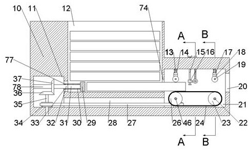
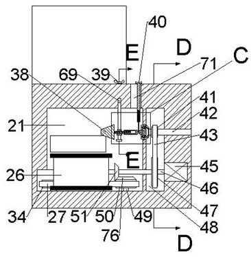
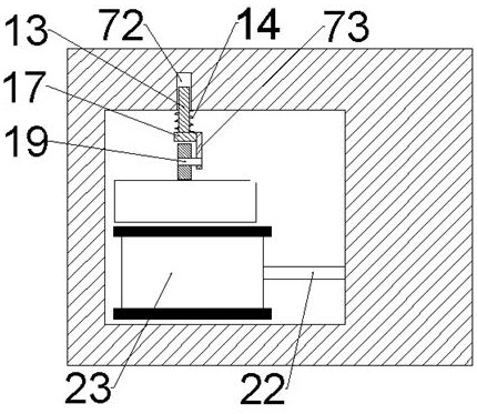
[0017]Combine belowFigure 1-6The present invention will be described in detail, in which, for the convenience of description, the following directions are specified as follows:figure 1 The vertical, horizontal, front and rear directions of the projection relationship are the same.

[0018]An automatic wood chamfering device described in conjunction with Figures 1-6 includes a main box body 10, the main box body 10 is provided with a pushing working cavity 11, the right side of the pushing working cavity 11 is connected with a pusher Block receiving cavity 33, the right side of the pushing block receiving cavity 33 is connected with a plate placing cavity 12, and the lower side of the pushing block receiving cavity 33 is provided with a belt transmission cavity 28 communicating with the pushing working cavity 11. The right side of the placing cavity 12 is connected with a steering limit cavity 74, the right side of the steering limit cavity 74 is connected with a working cavity 21, the ...


PUM


Abstract

The invention relates to the related field of wood processing, and discloses a full-automatic wood board chamfering device which comprises a main box body. A pushing working cavity is formed in the main box body; a pushing block storage cavity is formed in the right side of the pushing working cavity in a communicating mode; a board containing cavity is formed in the right side of the pushing block storage cavity in a communicating mode; a belt transmission cavity communicating with the pushing working cavity is formed in the lower side of the pushing block storage cavity; the right side of the board containing cavity communicates with a steering limiting cavity; the right side of the steering limiting cavity communicates with a working cavity; a plurality of wood boards with the same sizecan be assembled through the board containing cavity; each wood board needing to be machined can enter the working cavity through reciprocating motion of a push block; the wood board can enter the working cavity at a constant speed so as to be machined through transmission among a transmission belt wheel, a caterpillar band and a driven belt wheel and extrusion positioning of a friction wheel shaft on the wood board; a wood board chamfering function is achieved through rotation of a conical grinding wheel; a chamfering angle can be adjusted by rotating a rotary knob; and through all the abovemotion descriptions, a plurality of wood boards can be chamfered continuously and automatically.

Description

Technical field[0001]The invention relates to the related field of wood processing, in particular to an automatic wood board chamfering device.Background technique[0002]In the prior art, the process of chamfering the wood board usually adopts the worker's hand-held electric planer to work, the manual operation of the automatic chamfering machine, and the traditional manual tool to cut it. The above methods have the following wall ends: The electric planer is difficult to operate and it is difficult to control the accuracy. The manual operation of the automatic chamfering machine requires the worker to hold the wooden board with his hand to carry out each chamfering and also operate various instructions, which is more troublesome; it is more troublesome to use traditional tools. Cutting is time-consuming, laborious and difficult to maintain accuracy.Summary of the invention[0003]The purpose of the present invention is to provide a fully automatic wood board chamfering device, which c...

Claims


Application Information

Patent Timeline
IPC IPC(8): B24B9/18B24B41/00B24B47/12B24B47/22
CPCB24B9/18B24B41/005B24B47/12B24B47/22
Inventor 王思北
Owner 叶宇婷
Learn More