
Chamfering cutter, chamfering milling device and chamfering milling method

A technology of milling device and chamfering cutter, which is applied in the direction of milling cutter, milling machine equipment, milling machine equipment details, etc., can solve the problems of edge chamfering of parting surface, burr trimming, iron filings crushing the parting surface of workpiece, etc. Edge burrs, improve efficiency, improve the effect of workpiece product quality

Pending Publication Date: 2020-06-02
GUANGXI YUCHAI MASCH CO LTD
View PDF0 Cites 0 Cited by
  • Summary
  • Abstract
  • Description
  • Claims
  • Application Information

AI Technical Summary

Problems solved by technology

[0002] The current milling situation of the split face of the cylinder block is: the broach seat cannot follow the working slide to chamfer the edge of the split face of the workpiece, and can only mill the split face plane
When broaching the parting surface of the workpiece, the edge of the parting surface could not be chamfered. As a result, when the bearing cap is installed in the subsequent process, the mounting edge of the bearing cap will easily trim the burrs on the edge of the parting surface of the workpiece, and the falling iron chips will fall On the parting surface combined with the bearing cap, the iron filings crush the parting surface of the workpiece after the bearing cap is pressed.

Method used


Image

  • Chamfering cutter, chamfering milling device and chamfering milling method
  • Chamfering cutter, chamfering milling device and chamfering milling method
  • Chamfering cutter, chamfering milling device and chamfering milling method

Examples


Embodiment Construction

[0034] The present invention will be further described in detail below in combination with specific embodiments and with reference to the accompanying drawings. It should be emphasized that the following description is only exemplary and not intended to limit the scope of the invention and its application.

[0035] Non-limiting and non-exclusive embodiments will be described with reference to the following drawings, wherein like reference numerals refer to like parts unless specifically stated otherwise.

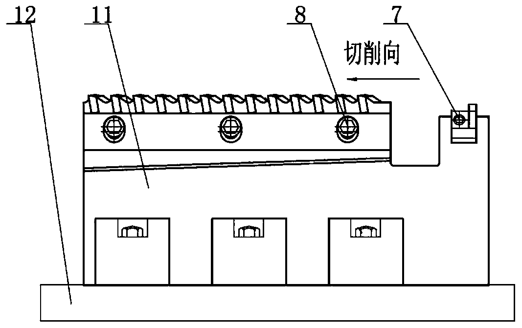
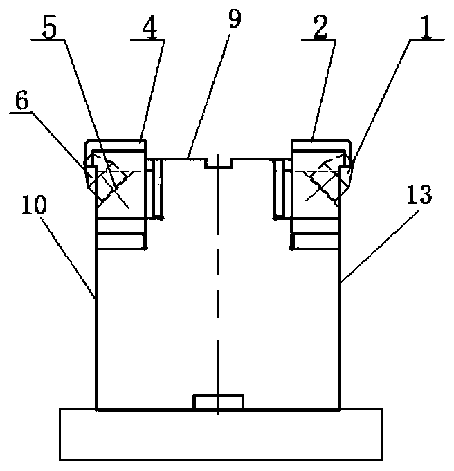
[0036] Such as figure 1 , figure 2 , diagram 2-1 A broach milling device with chamfering is shown, including a broach stand 11 and chamfering knives (1, 6) assembled on the broach stand 11. Both sides of the left part of the broach stand 11 are fixed with pulleys Knife (2,4), broach is fixed along the length direction of broach seat 11. The right part of broach seat 11 is equipped with described chamfering knife (1,6). Offer the fitting groove (15,16) that chamfering ...


PUM


Abstract

The invention discloses a chamfering cutter, a chamfering milling device and a chamfering milling method, which are used for realizing chamfering milling on the edge of a split surface of a cylinder body. The chamfering milling device comprise a broach seat and a chamfering cutter assembled on the broach seat, and assembling grooves for mounting the chamfering cutter are formed in corner angles ofthe upper end surface and the front side surface of the right part of the broach seat and corner angles formed by the upper end surface and the rear side surface; and the chamfering cutter is mountedin the assembling grooves. The chamfering cutter has the advantages of compact mechanism, adjustable chamfering depth, repeated regrinding use of a blade, convenience in replacement and adjustment and the like.

Description

technical field [0001] The invention relates to the technical field of engine accessories processing, in particular to a chamfering cutter, a chamfering milling device and a milling method. Background technique [0002] At present, the milling situation of the separated surface of the cylinder block is: the broach seat cannot follow the working slide table to chamfer the edge of the separated surface of the workpiece, and can only mill the separated surface plane. When broaching the parting surface of the workpiece, the edges of the parting surface were not chamfered, which resulted in the installation edge of the bearing cap easily cutting the burrs on the edge of the parting surface of the workpiece when the bearing cap was installed in the subsequent process, and the falling iron chips fell On the parting surface combined with the bearing cover, the iron filings crush the parting surface of the workpiece after the bearing cover is pressed. [0003] The disclosure of the ...

Claims


Application Information

Patent Timeline
Patent Type & Authority Applications(China)
IPC IPC(8): B23C5/22B23C3/12
CPCB23C3/126B23C5/2213
Inventor 曾赞李进杨靖益梁敏
Owner GUANGXI YUCHAI MASCH CO LTD
Learn More