A bottle wall automatic photo inspection equipment
A technology for testing equipment and bottle walls, which is applied in the field of bottle wall automatic photographing and testing equipment, can solve problems such as unstable preform fixation, poor detection accuracy, and unsmooth series connection, and achieve the effect of simple and ingenious structure, low cost, and ingenious structure
- Summary
- Abstract
- Description
- Claims
- Application Information
AI Technical Summary
Problems solved by technology
Method used
Image
Examples
Embodiment 1
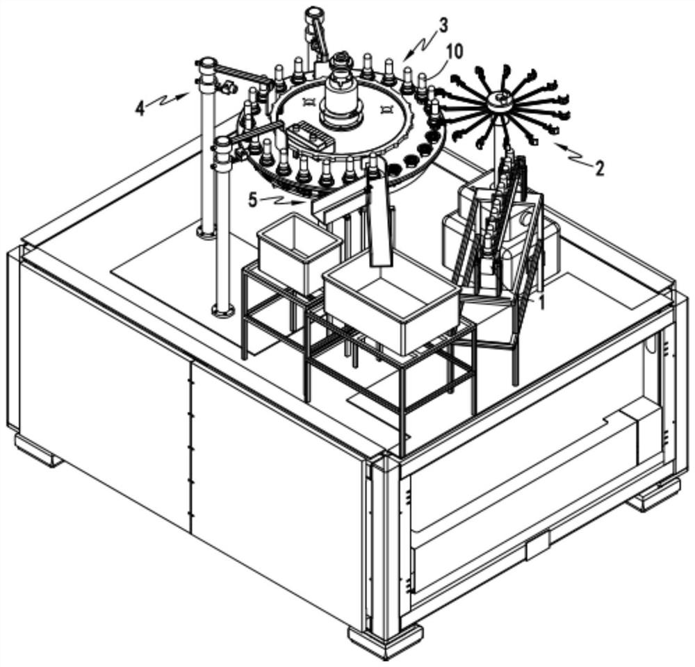
[0051] Such as Figure 1 to Figure 16 As shown, a bottle wall automatic photo-detection equipment includes a conveyor belt 1, the tail end of the conveyor belt 1 is provided with a transfer device 2, and one side of the transfer device 2 is provided with a rotating support device 3, the rotating A detection device 4 is provided on the rotation circle path of the support device 3, and an output device 5 is provided behind the detection device 4;
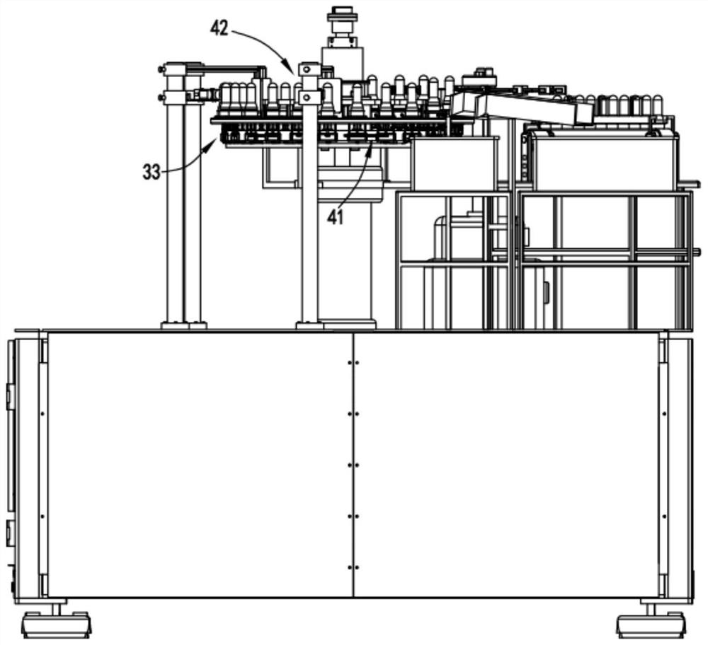
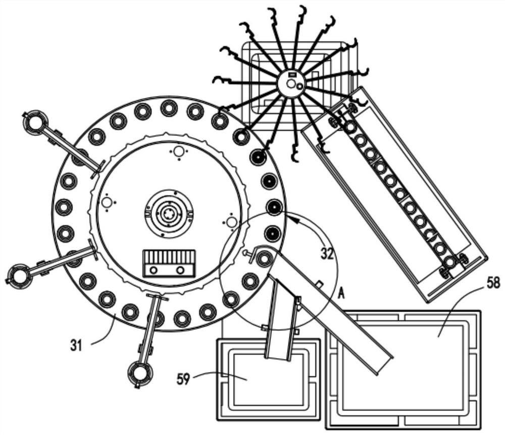
[0052] The rotating support device 3 includes a turntable 31, a plurality of supporting mechanisms 32 arranged in a circular array on the turntable 31, and a drive mechanism 33 arranged below the turntable 31, and the detection device 4 includes a rotating mechanism 41 and a photographing mechanism 42;
[0053] The handover device 2 transfers the preform 10 on the conveyor belt 1 to the support mechanism 32 located at the loading station 20, the support mechanism 32 supports the preform 10 to rotate under the drive of the turntable 31...
Embodiment 2
[0071] Such as image 3 with Figure 4 As shown, the components that are the same as or corresponding to those in the first embodiment are marked with the corresponding reference numerals in the first embodiment. For the sake of simplicity, only the differences from the first embodiment will be described below. The difference between the second embodiment and the first embodiment is that the output device 5 includes a guide channel 51 arranged on the side of the turntable 31, and the inlet end of the guide channel 51 is located at the output station 40 of the turntable 31 The end of the guide channel 51 is provided with an extension plate 52, and a push rod 53 is slidably arranged on the extension plate 52. One end of the push rod 53 is fixed with a push plate 54 and the other end is provided with a bump 55. A spring b56 sleeved on the push rod 53 is arranged between the protrusion 55 and the extension plate 52;
[0072] A ring member 57 is fixedly arranged on the turntable ...
PUM
 Abstract
Description
Claims
Application Information
 - R&D
- Intellectual Property
- Life Sciences
- Materials
- Tech Scout
- Unparalleled Data Quality
- Higher Quality Content
- 60% Fewer Hallucinations
Browse by: Latest US Patents, China's latest patents, Technical Efficacy Thesaurus, Application Domain, Technology Topic, Popular Technical Reports.
© 2025 PatSnap. All rights reserved.Legal|Privacy policy|Modern Slavery Act Transparency Statement|Sitemap|About US| Contact US: help@patsnap.com


