Engine mount structure of engine

An engine and machine foot technology, which is applied in the power plant, jet propulsion device, internal combustion propulsion device and other directions, can solve the problems of breakage of the suspension machine foot, heavy structure, welding, etc., to meet the supporting requirements, the structure is simple and reasonable, and the improvement The effect of reliability

Pending Publication Date: 2019-07-23
GUANGXI YUCHAI MASCH CO LTD
View PDF0 Cites 3 Cited by
  • Summary
  • Abstract
  • Description
  • Claims
  • Application Information

AI Technical Summary

Problems solved by technology

At present, most of the engine feet on the market are welded steel plates. This structure is heavy and has welding defects. The suspension feet of high-horsepower models and engineering vehicles are at risk of breaking; and for some supporting special vehicles, the power assembly The mounting end of the suspension machine foot and the mounting end of the suspension machine foot of the vehicle chassis are misaligned, the design and structure of the machine foot are complicated, and the overall strength after welding is difficult to guarantee

Method used


Image

  • Engine mount structure of engine
  • Engine mount structure of engine
  • Engine mount structure of engine

Examples


Embodiment Construction

[0015] The specific embodiments of the present invention will be described in detail below in conjunction with the accompanying drawings, but it should be understood that the protection scope of the present invention is not limited by the specific embodiments.

[0016] Unless expressly stated otherwise, throughout the specification and claims, the term "comprise" or variations thereof such as "includes" or "includes" and the like will be understood to include the stated elements or constituents, and not Other elements or other components are not excluded.

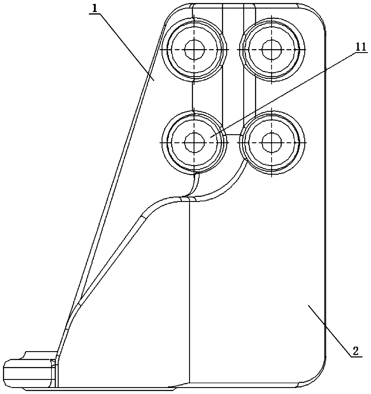
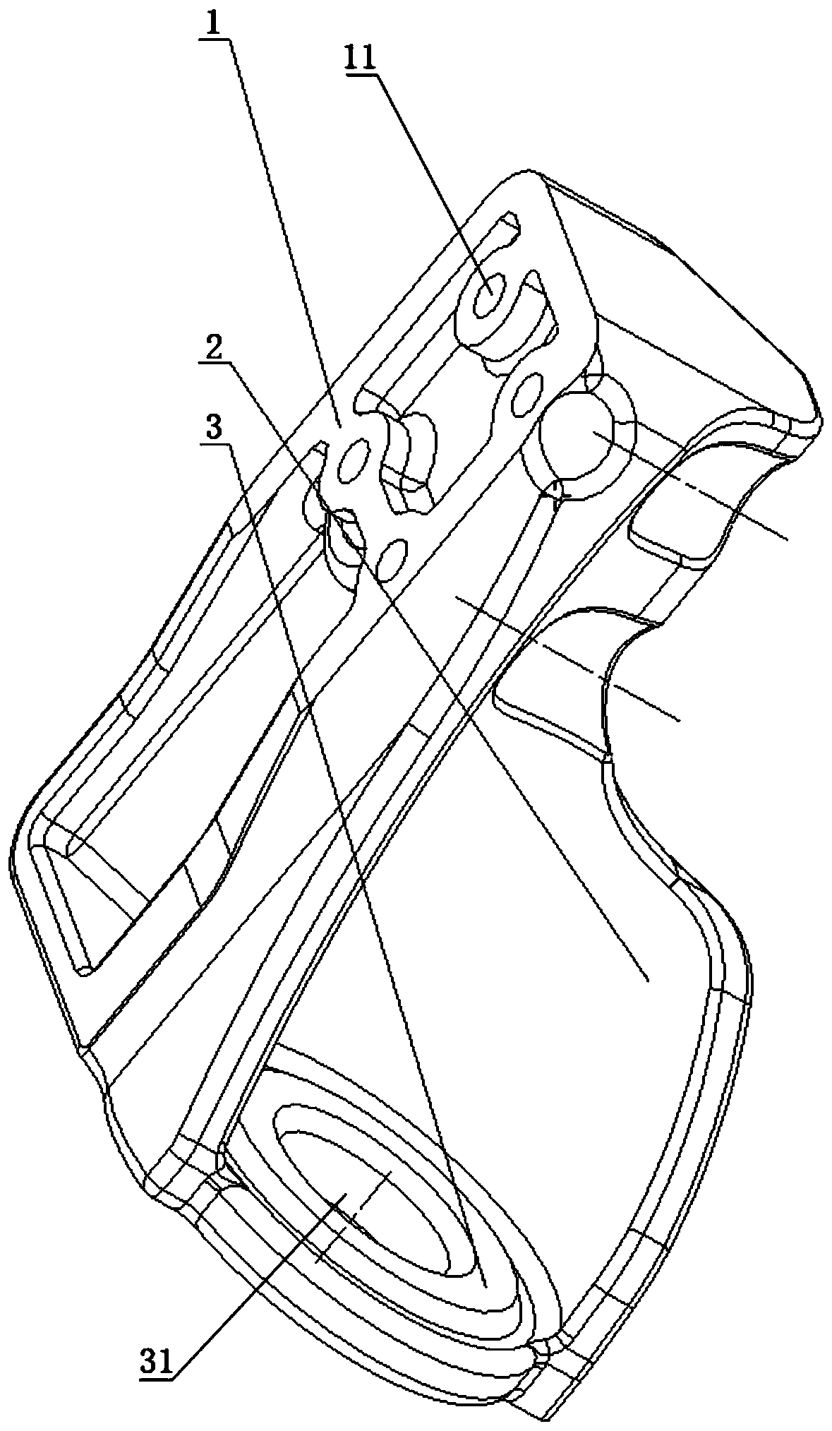
[0017] Such as Figure 1 to Figure 2 as shown, figure 1 It is a schematic diagram of the bottom structure of the machine foot structure of the engine according to an embodiment of the present invention; figure 2 It is a three-dimensional structure schematic diagram of the machine foot structure of the engine according to an embodiment of the present invention.

[0018] A machine foot structure of an engine according to ...


PUM


Abstract

The invention discloses an engine mount structure of an engine. The engine mount structure comprises a mounting flat plate, side skirt parts and a fixing plate; the upper end of the mounting flat plate is fixedly connected with an air cylinder body or a flywheel casing; the side skirt parts are fixedly connected with the lower end of the mounting flat plate, and the side skirt parts are semicircular; and the fixing plate is fixed between the lower end of the mounting flat plate and the upper ends of the side skirt parts, and used for being fixedly connected with a vehicle chassis. Thus, according to the engine mount structure of the engine, the structure is simple and reasonable, the matching need is met, and the engine mount strength and the mounting reliability of a power assembly are improved.

Description

technical field [0001] The invention relates to the technical field of engines, in particular to an engine machine foot structure. Background technique [0002] At present, there are various non-road, commercial, passenger and other vehicle engines in the market, and most of the engines are supported by 4-point mounts. The same vehicle chassis is equipped with different types of engines, which need to be installed and matched at the engine power interface and engine suspension support. It is relatively difficult to change the chassis interface of the vehicle at the vehicle end, while the change at the engine power end is relatively simple for the complete vehicle, such as changing the flywheel, flywheel housing, engine mount, etc. At present, most of the engine feet on the market are welded steel plates. This structure is heavy and has welding defects. The suspension feet of high-horsepower models and engineering vehicles are at risk of breaking; and for some supporting spe...

Claims


Application Information

Patent Timeline
Patent Type & Authority Applications(China)
IPC IPC(8): B60K5/12
CPCB60K5/12
Inventor 赵泉卢年红钟秀俊刘振锋黄幼林
Owner GUANGXI YUCHAI MASCH CO LTD
Why Eureka
Try Eureka