Fabricated buckling restraint supporting component

A technology of buckling restraint and supporting components, which is applied in the direction of building components, building structures, protective buildings/shelters, etc., can solve the problems of increasing structural load, long processing time, inconvenience in construction, transportation and installation, and achieve reduction The effect of maintenance costs

Pending Publication Date: 2019-07-23
HUNAN UNIV
View PDF0 Cites 0 Cited by
  • Summary
  • Abstract
  • Description
  • Claims
  • Application Information

AI Technical Summary

Problems solved by technology

The traditional grouting-type buckling-constrained support members are filled with solid fillers in the constrained part, which leads to the overall weight of the support members, which causes inconvenience to construction, transportation and installation, and also increases the load of the structure during the reinforcement project. In addition, during the processing In the process, the core plate and sleeve must be made first, then the filling material is poured, and finally closed, and the processing time is longer

Method used


Image

  • Fabricated buckling restraint supporting component
  • Fabricated buckling restraint supporting component
  • Fabricated buckling restraint supporting component

Examples


Embodiment 1

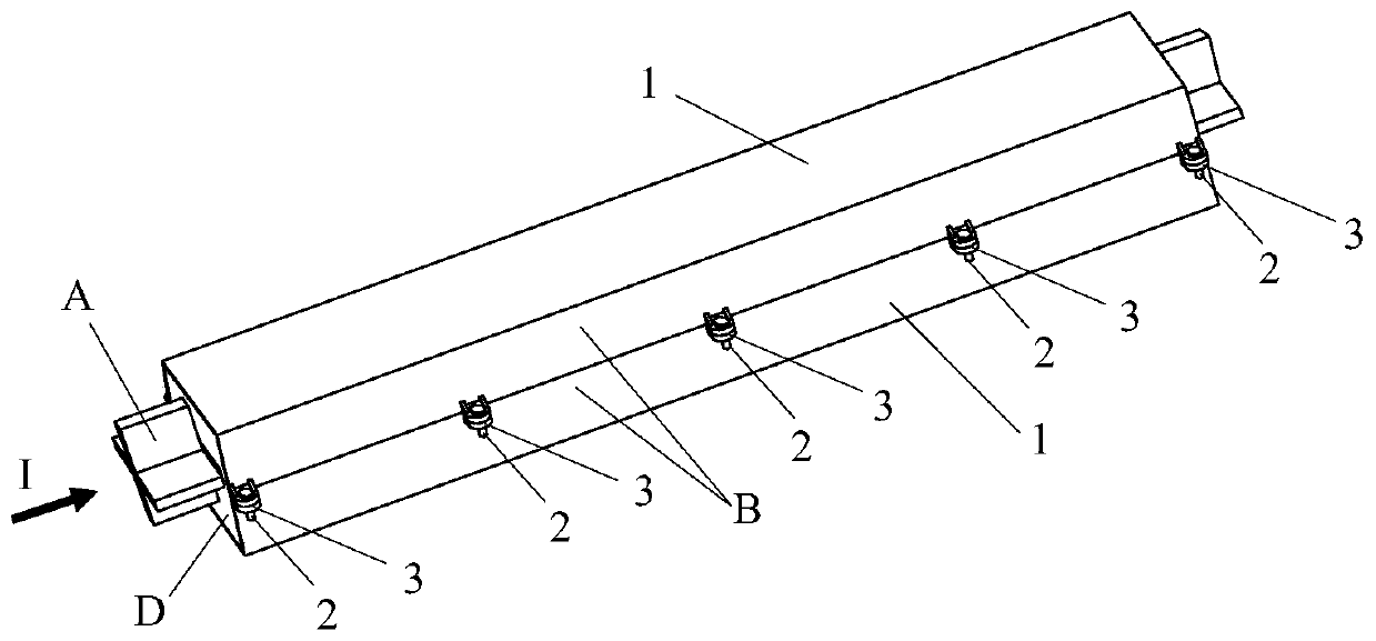
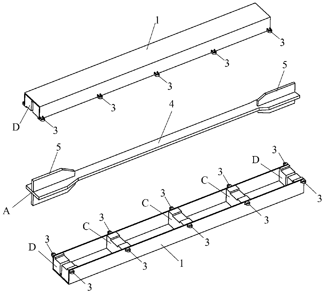
[0025] see Figure 1-8 , this embodiment 1 includes a core unit A, an outer restraint steel pipe B, an inner restraint card C and an end restraint card D, and the outer restraint steel pipe B is assembled by connecting two identical half steel pipes 1 through a bolt connection pair 2 , there are several pairs of internal constraint cards C, which are equidistantly arranged in pairs in the two half-side steel pipes 1, and the specific number is determined by the length of the core unit A and calculated according to the pressure bar stability theory to ensure that the core unit is not free from The compression buckling is determined. There are two pairs of the end restraints D, which are arranged at both ends of the two half steel pipes 1. The internal restraint C and the end restraint D are welded to the two half steel pipes 1. connected.

[0026] A pair of lug plates 3 are welded on the outer sides of the two edges of the two half-side steel pipes 1 corresponding to the inter...

Embodiment 2

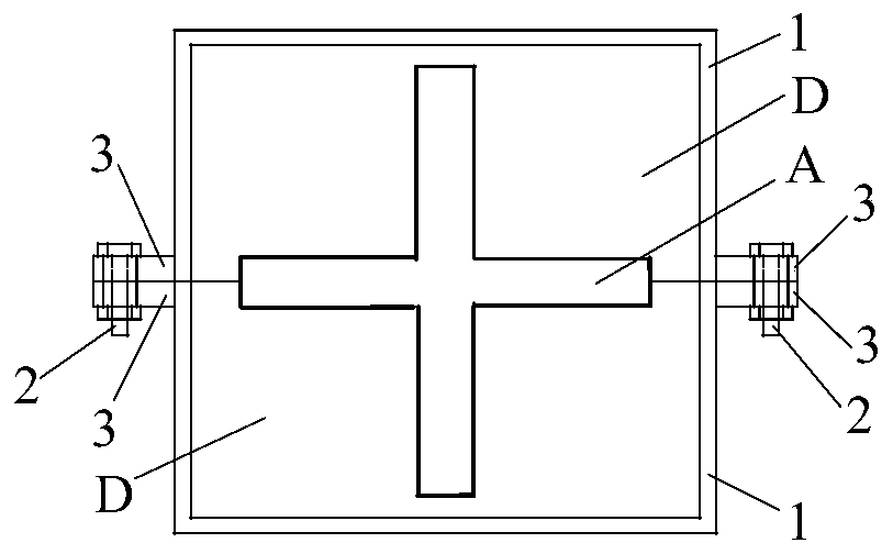
[0032] see Figure 1-2 , Figure 7-9 , this embodiment 2 is basically the same as embodiment 1, the difference is that the section of the working section 4 of the core unit is cross-shaped, and the shape and size of the corresponding internal constraint card notch 6 match the section shape and size of the working section 4 of the core unit.

Embodiment 3

[0034] see Figure 10 , Figure 11 , this embodiment 3 is basically the same as embodiment 1, the difference is that the cross-section of the outer restraint steel pipe B is circular, and the outer contour shape and size of the corresponding inner restraint card C and end restraint card D are the same as the internal shape and size of the half steel pipe 1 match.


PUM


Abstract

The invention relates to a fabricated buckling restraint supporting component, which includes a core unit, an outer restraint steel pipe, a plurality of pairs of inner restraint clamps and two pairs of end restraint clamps. The outer restraint steel pipe is composed of two identical half-edge steel pipes connected and assembled through a bolt pair, the inner restraint clamps are arranged in pairsin the two half-edge steel pipes at equal distance, it is ensured that the core unit does not buckle under compression, the end restraint clamps are arranged at both ends in the two half-edge steel pipes, and the inner restraint clamps and the end restraint clamps are connected with the two half-edge steel pipes by welding. According to the fabricated buckling restraint supporting component, afterthe yield failure occurs due to axial tension and compression of the core unit, the bolt connection pair can be taken down and unscrewed to replace the core unit, the outer restraint steel pipe, theinner restraint clamps and the end restraint clamps which are reused are retained, thus the post-disaster maintenance cost is lowered, the dead weight is low, steel is saved, and manufacturing and installation are convenient.

Description

technical field [0001] The invention belongs to the technical field of anti-seismic and energy-dissipating shock absorption of engineering structures, and in particular relates to an assembled buckling-constrained support member. Background technique [0002] Buckling-constrained bracing, because its core force-bearing unit has external restraint units to provide lateral support, can prevent buckling failure of the core unit when it is under compression, and the axial tension and compression of the support can reach the section yield force of the core unit, and the tension and compression of the member The bearing capacity is close, which greatly improves the utilization rate of steel. In an earthquake, after the buckling-constrained support core unit yields in tension and compression, plastic deformation can occur to consume seismic energy, reducing or avoiding damage to the main structural components, so the main structure is protected, which is extremely beneficial for ea...

Claims


Application Information

Patent Timeline
Patent Type & Authority Applications(China)
IPC IPC(8): E04B1/98E04H9/02E04B1/343
CPCE04B1/34326E04H9/021
Inventor 贺拥军周绪红王继新陈兴发
Owner HUNAN UNIV
Why Eureka
Try Eureka