
A centrifugal slag discharge type radial piston chuck, power head and drilling rig

A technology of centrifugal slag discharge and power head, applied in drill pipe, drill pipe, earthwork drilling, etc., can solve the problems of easy accumulation of rock powder, slow response of chuck opening, etc., and achieve easy maintenance, simple structure and reliability. strong effect

Active Publication Date: 2020-08-28
XIAN RES INST OF CHINA COAL TECH& ENG GROUP CORP
View PDF10 Cites 0 Cited by
  • Summary
  • Abstract
  • Description
  • Claims
  • Application Information

AI Technical Summary

Problems solved by technology

[0010] The first object of the present invention is to provide a centrifugal slag discharge type radial piston chuck, which solves the problems of slow chuck opening response and easy accumulation of cinder and rock powder inside the chuck in existing piston chucks. Simple, easy maintenance operation

Method used


Image

  • A centrifugal slag discharge type radial piston chuck, power head and drilling rig
  • A centrifugal slag discharge type radial piston chuck, power head and drilling rig

Examples


Embodiment 1

[0045] Embodiment 1. Centrifugal slag discharge type radial piston chuck:

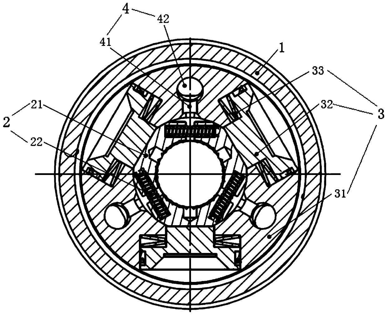
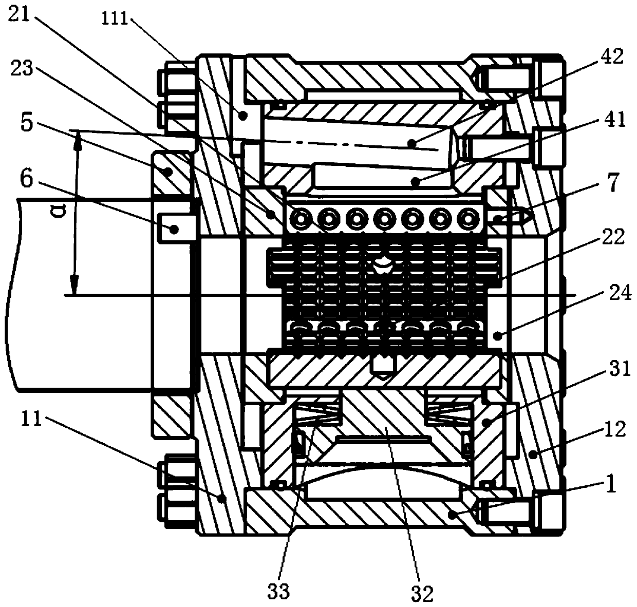
[0046] combine figure 1 and figure 2 , the centrifugal slag discharge type radial piston chuck of the present embodiment includes a chuck body 1, a slip assembly 2 and a radial power assembly 3 are arranged radially in the chuck body 1, and a radial power assembly 3 is arranged along the shaft A centrifugal slag discharge combination chamber 4 is provided in the direction of the rotating centrifugal force, connecting the slip assembly 2 with the external space.

[0047] The slip assembly 2 is provided with three groups of slips 21 along the circumferential direction for clamping the drill pipe; a return spring 22 is provided between adjacent slips 21; the radial power assembly 3 includes a radial oil cylinder 31 and a radial piston 32 And the disc spring 33, the outer middle planes of the three slips 21 are respectively in contact with the ends of the three radial pistons 32, and the three radial pi...


PUM


Abstract

The invention discloses a centrifugal deslagging type radial piston chuck, a power head and a drilling machine. The centrifugal deslagging type radial piston chuck comprises a chuck body; and a slip assembly and a radial power assembly are sequentially arranged in the chuck body in the radial direction. The centrifugal deslagging type radial piston chuck is characterized in that the radial power assembly and the slip assembly are of a split force-transmitting structure; the slip assembly comprises a plurality of slips which are arranged in the circumferential direction; the adjacent slips areconnected through reset springs, and centrifugal deslagging combined cavities are formed corresponding to gaps of the adjacent slips; and the centrifugal deslagging combined cavities are formed in theaxial rotation centrifugal force direction of the chuck body. According to the centrifugal deslagging type radial piston chuck, the problems that as for a traditional piston type chuck, internal coalslag and rock powder are stacked, and consequently the chuck cannot work normally can be solved; and meanwhile the problem that responding is slow when the chuck is loosened is solved, the structureis simple, maintenance is easy, and reliability is high.

Description

technical field [0001] The patent of the invention belongs to the field of hydraulic chucks of tunnel drilling rigs, and relates to a centrifugal slag discharge type radial piston chuck, a power head and a drilling rig. Background technique [0002] The chuck is an important component of the drilling rig. It is installed on the power head and used as a clamping device for the drilling rig. The chuck is mainly used to clamp the drilling tool and provide torque and axial force to the drilling tool. [0003] At present, the common hydraulic chucks of tunnel drilling rigs mainly include rubber cylinder type, inclined plane booster type and piston type hydraulic chucks. Among them, the piston hydraulic chuck has gradually become a new hotspot in hydraulic chuck research due to its advantages of high reliability, high efficiency, and low maintenance cost. [0004] There are still some deficiencies in the existing common piston hydraulic chuck technology, which cannot satisfy the ...

Claims


Application Information

Patent Timeline
Patent Type & Authority Patents(China)
IPC IPC(8): E21B19/10
CPCE21B19/10
Inventor 李坤彭涛梁春苗宋海涛姚亚峰王毅韩健王普
Owner XIAN RES INST OF CHINA COAL TECH& ENG GROUP CORP
Learn More