
Nondestructive detection system for vacuum acoustic emission

A technology of acoustic emission testing and non-destructive testing, applied in the direction of measuring devices, applying stable tension/pressure to test material strength, instruments, etc., can solve the problem of the difficulty of observing the cracking process of coating materials in detail, the limitation of spraying thickness, and the inability to effectively observe To the initiation and propagation mechanism of coating material cracks, material damage mechanism and other issues

Inactive Publication Date: 2019-07-23
ARMOR ACADEMY OF CHINESE PEOPLES LIBERATION ARMY
View PDF14 Cites 1 Cited by
  • Summary
  • Abstract
  • Description
  • Claims
  • Application Information

AI Technical Summary

Problems solved by technology

[0003] Since the coating materials are mostly prepared by plasma spraying or physical vapor deposition, due to the particularity of the spraying method, the spraying thickness of the coating material may be limited. For example, the spraying thickness of some ceramic coating materials is generally several In the range of ten microns to several millimeters, due to the small thickness, it is difficult to observe the cracking process of the coating material in detail even with a high-resolution camera at the macro scale, and it is impossible to effectively observe the coating material during the stretching process. The mechanism of crack initiation and propagation in medium and the damage mechanism of materials

Method used


Image

  • Nondestructive detection system for vacuum acoustic emission
  • Nondestructive detection system for vacuum acoustic emission
  • Nondestructive detection system for vacuum acoustic emission

Examples


Embodiment Construction

[0031] Embodiments of the present invention are described in detail below, examples of which are shown in the drawings, wherein the same or similar reference numerals designate the same or similar elements or elements having the same or similar functions throughout. The embodiments described below by referring to the figures are exemplary only for explaining the present invention and should not be construed as limiting the present invention.

[0032] In describing the present invention, it should be understood that the terms "center", "longitudinal", "transverse", "length", "width", "thickness", "upper", "lower", "front", " Back", "Left", "Right", "Vertical", "Horizontal", "Top", "Bottom", "Inner", "Outer", "Clockwise", "Counterclockwise", "Axial" , "radial", "circumferential" and other indicated orientations or positional relationships are based on the orientations or positional relationships shown in the drawings, which are only for the convenience of describing the present ...


PUM


Abstract

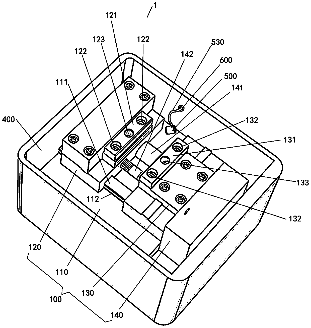
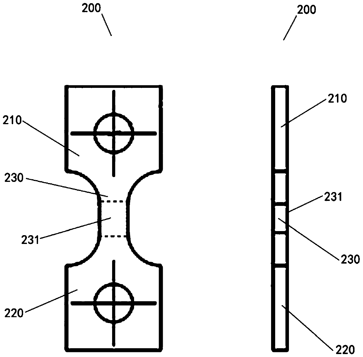
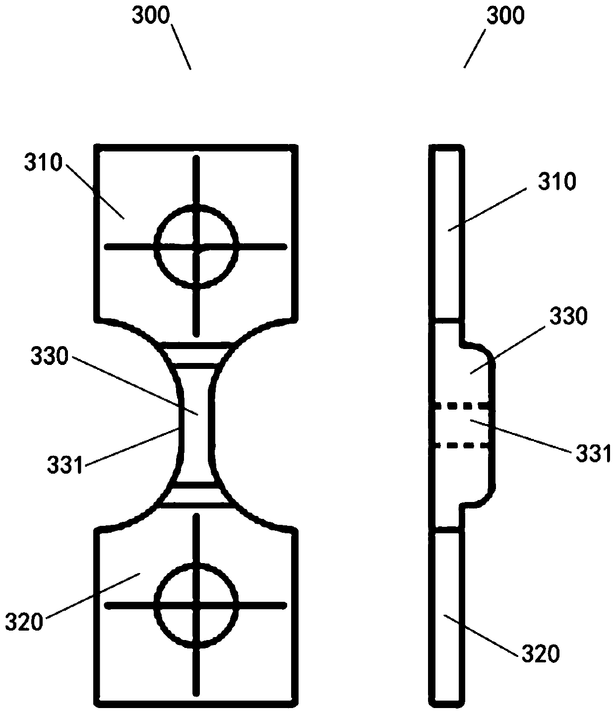
The invention discloses a nondestructive detection system for vacuum acoustic emission. The nondestructive detection system comprises an in-situ stretcher, a sample matrix, a scanning electron microscope, a computer system, an acoustic emission detection probe, a signal amplifier and a signal processor, wherein the sample matrix is fixed on the in-situ stretcher; the scanning electron microscope is provided with a vacuum sample bin; the in-situ stretcher is arranged in the vacuum sample bin; the computer system is connected with each of the scanning electron microscope and the in-situ stretcher; the acoustic emission detection probe is arranged in the vacuum sample bin and is in contact with the sample matrix; the signal amplifier is arranged outside the vacuum sample bin and is connectedwith the acoustic emission detection probe through a cable; and the signal processor is connected with the signal amplifier. According to the nondestructive detection system for vacuum acoustic emission, the cracking processes of coating materials can be detailedly observed while realizing the nondestructive detection of acoustic emission, so that benefit is brought to analyze the initiation and expansion mechanism of cracks of the coating materials in the stretching process and the damage mechanism of the materials.

Description

technical field [0001] The invention relates to the field of nondestructive testing, in particular to a vacuum acoustic emission nondestructive testing system. Background technique [0002] In related technologies, the detection of mechanical properties of coating materials and the exploration of damage mechanisms are usually carried out on a macro scale by using a universal tensile testing machine. The image correlation method measures the strain change on the front surface of the coating. [0003] Since the coating materials are mostly prepared by plasma spraying or physical vapor deposition, due to the particularity of the spraying method, the spraying thickness of the coating material may be limited. For example, the spraying thickness of some ceramic coating materials is generally several In the range of ten microns to several millimeters, due to the small thickness, it is difficult to observe the cracking process of the coating material in detail even with a high-reso...

Claims


Application Information

Patent Timeline
Patent Type & Authority Applications(China)
IPC IPC(8): G01N3/08G01N3/06
CPCG01N3/08G01N3/06G01N2203/0017G01N2203/0064G01N2203/0066G01N2203/0244G01N2203/0298G01N2203/0641G01N2203/0658
Inventor 底月兰王海斗董丽虹邢志国刘明王乐刘韬
Owner ARMOR ACADEMY OF CHINESE PEOPLES LIBERATION ARMY
Learn More