Primary wind speed wear-resistant type measuring device

A measurement device and wind speed technology, which is applied in the direction of measuring fluid velocity by using pressure difference, can solve the problems of affecting accuracy, unstable air flow, and the problem of blockage of primary measurement components cannot be fundamentally solved, so as to prolong the service life and increase the service life Effect

Pending Publication Date: 2019-07-23
大唐双鸭山热电有限公司
View PDF0 Cites 1 Cited by
  • Summary
  • Abstract
  • Description
  • Claims
  • Application Information

AI Technical Summary

Problems solved by technology

[0002] With the advancement of science and technology and the continuous improvement of the automation level of thermal power plants, the requirements for the input rate of automatic adjustment of air volume in each power plant are also increasing; the types of air volume measurement devices commonly used at present are: airfoil type, Venturi and bar type ( Annubar, Weiliba) and other types; due to the limited space of air duct layout of some power plant units, there are not enough straight pipe sections, resulting in unstable air flow and large differences between cold and hot states of the flow field, which in turn affects the accuracy of measurement; In addition, the hot air (or mixed air) is a dust-laden air flow. The pressure-sensitive body of the above-mentioned commonly used air volume measurement device is a space with a pressure-sensing hole, and the dust can only enter and not exit, which is easy to cause blockage, which makes the blockage of the primary element measured The problem cannot be solved fundamentally

Method used


Image

  • Primary wind speed wear-resistant type measuring device
  • Primary wind speed wear-resistant type measuring device
  • Primary wind speed wear-resistant type measuring device

Examples


Embodiment Construction

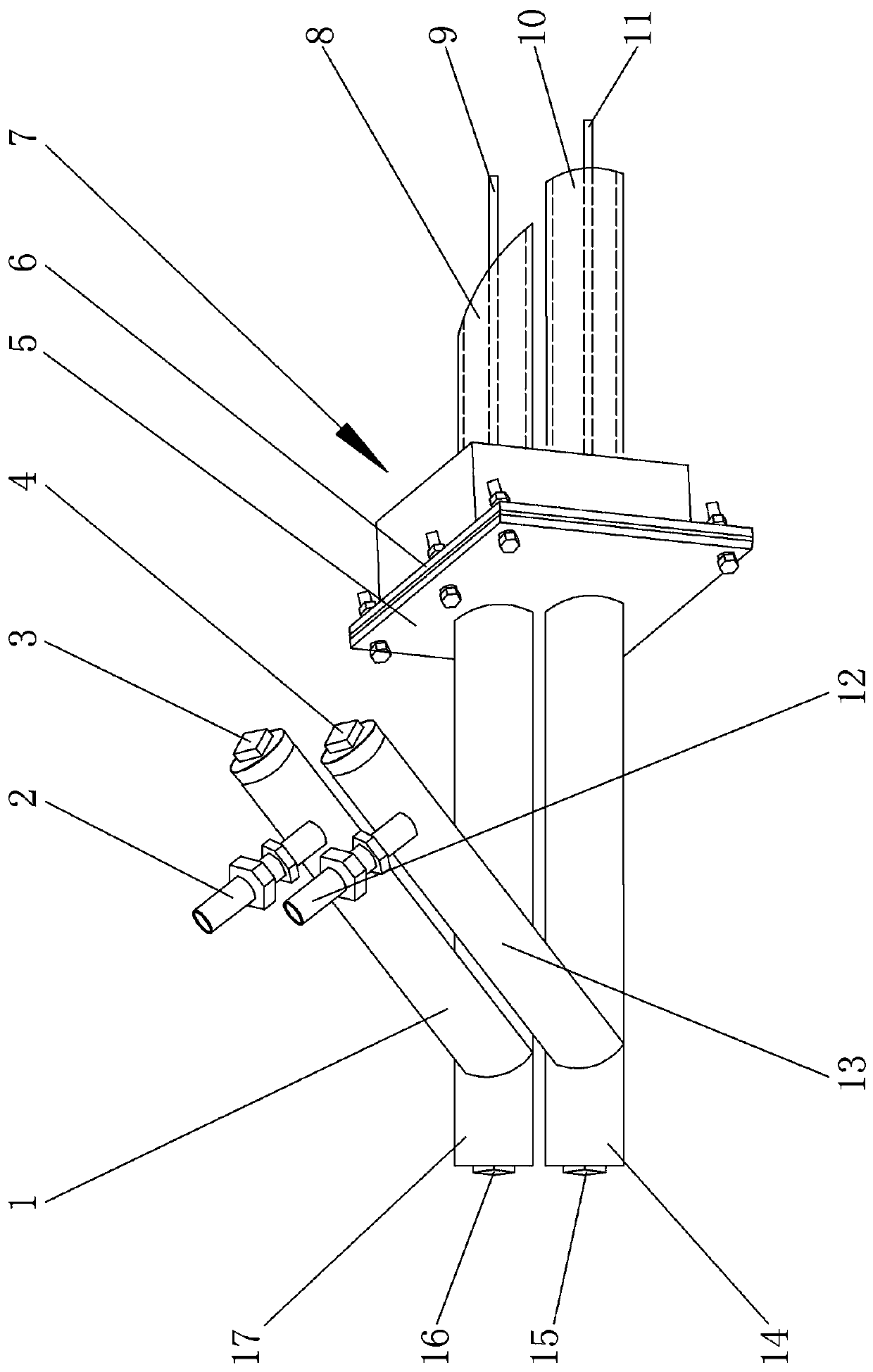
[0022] The specific embodiment of the present invention is, with reference to figure 1 , including the windward sampling pipe 17, the leeward sampling pipe 14, the secondary sedimentation chamber 1 of the windward pipe, the secondary sedimentation chamber 13 of the leeward pipe, the windward pressure joint 2, the leeward pressure joint 12, the flange 5, the fixing seat 7, the windward Probe 8, leeward probe 10, windward rapping rod 9, leeward rapping rod 11, wherein, one end of the windward sampling pipe 17 has a sealing plug 16, and the other end of the windward sampling pipe 17 is connected to the flange 5 , one end of the secondary sedimentation chamber 1 of the windward pipe communicates with the windward sampling pipe 17 at an angle of 40° at the end of the sealing plug 16, and the secondary sedimentation chamber 1 of the windward pipe is connected with the windward sampling pipe 17. There is a throttling orifice, the other end of the secondary sedimentation chamber 1 of ...


PUM


Abstract

The invention relates to a primary wind speed wear-resistant type measuring device. The primary wind speed wear-resistant type measuring device comprises a windward sampling tube, a leeward sampling tube, a windward tube secondary sediment chamber, a leeward tube secondary sediment chamber, a windward pressure leading joint, a leeward pressure leading joint, a flange, a fixed seat, a windward probe, a leeward probe, a windward vibration beating rod and a leeward vibration beating rod. The primary wind speed wear-resistant type measuring device has the beneficial effects that the windward sampling tube and the leeward sampling tube are fixedly installed on the fixed base and are separated by the fixed base, the back-to-back welding of two sampling tubes is replaced, inaccurate sampling dataof the sampling tubes due to the fact that the positions of the sampling tubes are unstable relative to an air duct is avoided; the sampling probes adopt wear-resistant ceramic materials, the servicelife of the sampling tubes is prolonged, and the service cycle is prolonged; the angle between the sampling tubes and a secondary ash settling chamber is 40 degrees, the sampling tubes communicate with the secondary ash settling chamber, a pressure leading tube communicates with the secondary ash settling chamber, secondary ash settling is achieved, the measurement accuracy is ensured, and ash isprevented from entering a pressure differential transmitter.

Description

technical field [0001] The invention relates to a wind speed measuring device in a pipeline, in particular to a primary wind speed wear-resistant measuring device. Background technique [0002] With the advancement of science and technology and the continuous improvement of the automation level of thermal power plants, the requirements for the input rate of automatic adjustment of air volume in each power plant are also increasing; the types of air volume measurement devices commonly used at present are: airfoil type, Venturi and bar type ( Annubar, Weiliba) and other types; due to the limited space of air duct layout of some power plant units, there are not enough straight pipe sections, resulting in unstable air flow and large differences between cold and hot states of the flow field, which in turn affects the accuracy of measurement; In addition, the hot air (or mixed air) is a dust-laden air flow. The pressure-sensitive body of the above-mentioned commonly used air volum...

Claims


Application Information

Patent Timeline
Patent Type & Authority Applications(China)
IPC IPC(8): G01P5/14
CPCG01P5/14
Inventor 朱佰英
Owner 大唐双鸭山热电有限公司
Why Eureka
Try Eureka