
Lining plate mounting structure for mixing machine

A technology of installation structure and mixer, which is applied in the direction of mixer, transportation and packaging, mixer accessories, etc., can solve the problems of unreasonable installation structure, affecting production efficiency, poor granulation effect, etc., achieve simple structure and improve disassembly efficiency , easy to replace the effect

Pending Publication Date: 2019-07-26
LAIWU IRON & STEEL GRP
View PDF0 Cites 0 Cited by
  • Summary
  • Abstract
  • Description
  • Claims
  • Application Information

AI Technical Summary

Problems solved by technology

[0003] The existing liners generally use nylon or ceramic liners, and the installation structure is not very reasonable. During the operation of the mixer, there will be sticky materials on the cylinder wall, material rejection at the feed port, and serious wear of the liners, resulting in poor mixing effect. , poor granulation effect and other defects, affecting production efficiency
[0004] Therefore, how to overcome defects such as poor mixing effect of the current mixer, sticky material on the cylinder wall, material rejection at the feed inlet, serious wear of the lining plate, and short service life have become technical problems to be solved urgently by those skilled in the art.

Method used


Image

  • Lining plate mounting structure for mixing machine
  • Lining plate mounting structure for mixing machine
  • Lining plate mounting structure for mixing machine

Examples


Embodiment Construction

[0022] The technical solutions in the embodiments of the present invention will be clearly and completely described below in conjunction with the accompanying drawings in the embodiments of the present invention. Obviously, the described embodiments are only some, not all, embodiments of the present invention. Based on the embodiments of the present invention, all other embodiments obtained by persons of ordinary skill in the art without making creative efforts belong to the protection scope of the present invention.

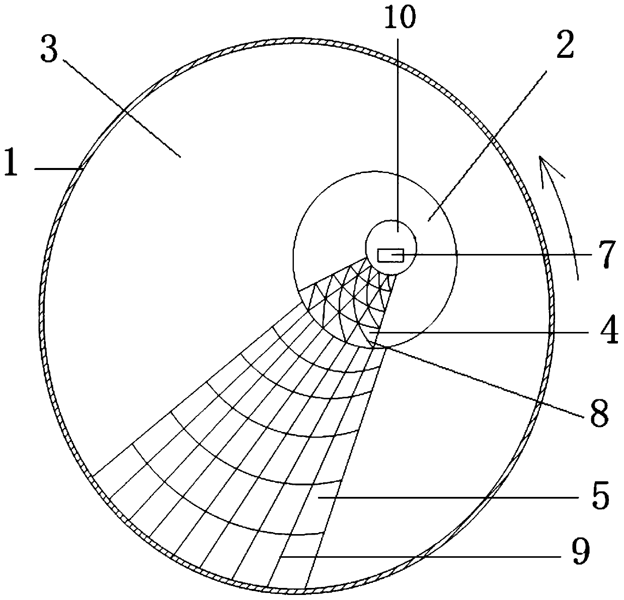
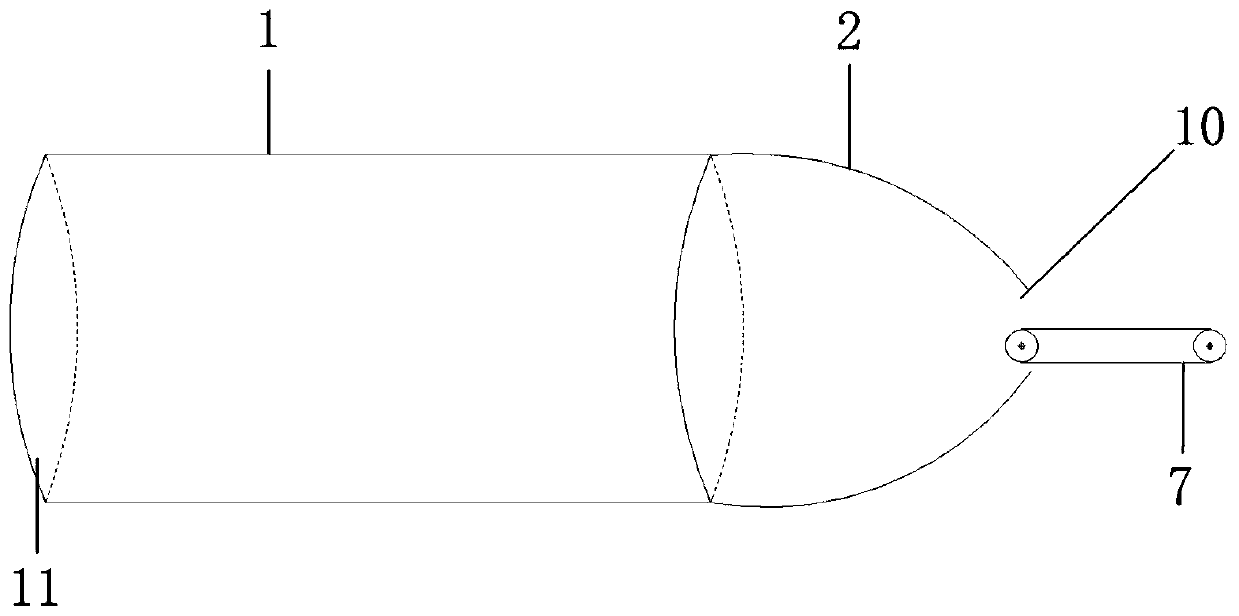
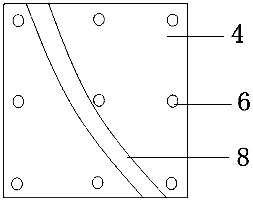
[0023] Such as Figure 1-6 As shown, a liner plate installation structure for a mixer, including a cylinder 1, a cylinder arc surface part 3 inside the cylinder 1, and a hemispherical surface part 2 at the feed inlet 10 connected to the cylinder arc surface part 3, a hemisphere The surface part 2 is evenly fixed with a plurality of lining boards 14, and the lining board 14 is provided with a guide strip 8 consistent with the rotation direction of the cylinder 1,...


PUM


Abstract

The invention discloses a lining plate mounting structure for a mixing machine. The lining plate mounting structure comprises a cylinder, a cylinder arc surface portion on the inner side of the cylinder, and a hemispherical surface portion at a feed inlet. A plurality of first lining plates are evenly fixed to the hemispherical surface portion that is partially connected with the cylinder arc surface portion. First flow guide strips, identical to the cylinder in rotation direction, are arranged on the first lining plates, and are in the form of arcs on the first lining plates. A plurality of second lining plates are evenly fixed to the cylinder arc surface portion. Second flow guide strips, identical to the cylinder in axial direction, are arranged on the second lining plates, and are in the form of straight lines on the second lining plates. The designed lining plate mounting structure based on mixed use of the first lining plates and the second lining plates plays a flow guide role in the movement direction of materials, so that the defects such as abrasion of the first lining plates and the second lining plates by the materials, poor mixing effect, material adhesion to cylinderwalls, and material throwing at the feed inlet are reduced. The lining plate mounting structure is simple, convenient to manufacture and resistant to abrasion, accessories are easy to replace, consumption of the accessories is low, and the service life is long, so that the lining plate mounting structure is suitable for wide promotion.

Description

technical field [0001] The invention relates to the technical field of mixers, in particular to a lining plate installation structure for mixers. Background technique [0002] At this stage, the primary and secondary cylinder mixers in the sintering area of ​​iron and steel enterprises are installed with wear-resistant liners for protection in order to prevent the materials from wearing and tearing the inner wall of the cylinder during the process of mixing materials. [0003] The existing liners generally use nylon or ceramic liners, and the installation structure is not very reasonable. During the operation of the mixer, there will be sticky materials on the cylinder wall, material rejection at the feed port, and serious wear of the liners, resulting in poor mixing effect. , Poor granulation effect and other defects affect production efficiency. [0004] Therefore, how to overcome defects such as poor mixing effect of current mixers, sticky material on the cylinder wall, ...

Claims


Application Information

Patent Timeline
IPC IPC(8): B01F15/00
CPCB01F35/511
Inventor 刘磊
Owner LAIWU IRON & STEEL GRP
Learn More