Oil smoke purification system

An oil fume purification and oil fume technology, which is applied in chemical instruments and methods, external electrostatic separators, electrode structures, etc., can solve the problems of oil fume deposition in oil fume pipes, and achieve the effects of improving purification capacity, avoiding deposition, and ingenious structural design.

Pending Publication Date: 2019-07-26
北京圣喻环保科技有限公司
View PDF0 Cites 0 Cited by
  • Summary
  • Abstract
  • Description
  • Claims
  • Application Information

AI Technical Summary

Problems solved by technology

[0005] In order to solve the problem of oil fume deposition in the oil fume pipe caused by the electrostatic oil fume purifier in the prior art, which can only be installed at the end of the oil fume pipe, a kind of oil fume purification equipment is proposed, which can be installed at the front end of the oil fume pipe to solve the problem of oil fume deposited in the oil fume pipe. Improve oil fume purification ability

Method used


Image

  • Oil smoke purification system
  • Oil smoke purification system
  • Oil smoke purification system

Examples


Embodiment 1

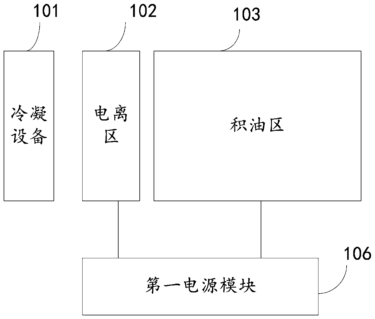
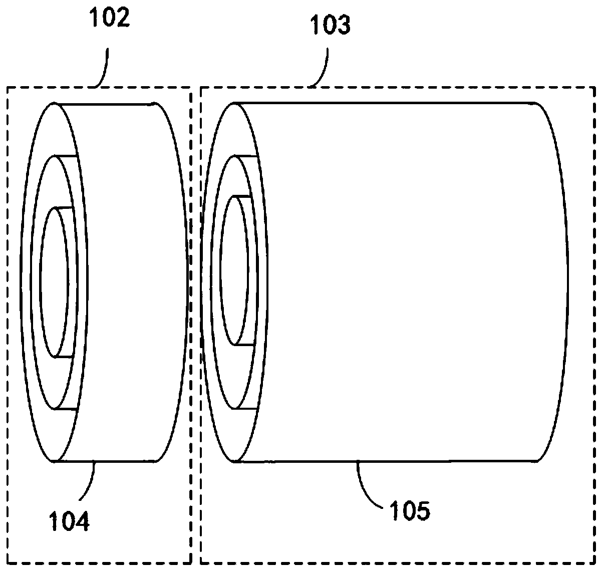
[0050] refer to figure 1 and figure 2 , this embodiment provides an oil fume purification system, including a condensing device 101, an ionization area 102, and an oil accumulation area 103 arranged in sequence;

[0051] The ionization region 102 includes a plurality of first conductive cylinders 104 with open ends, the plurality of first conductive cylinders 104 are arranged concentrically, and a space for air flow to pass is formed between adjacent first conductive cylinders 104;

[0052]The oil accumulation area 103 includes a plurality of second conductive cylinders 105 with openings at both ends, the plurality of second conductive cylinders 105 are arranged concentrically, and a space for airflow to pass is formed between adjacent second conductive cylinders 105;

[0053] The ionization region 102 is used to form a first electric field between adjacent first conductive cylinders 104 under the action of a first voltage;

[0054] The oil accumulation area 103 is used to ...

Embodiment 2

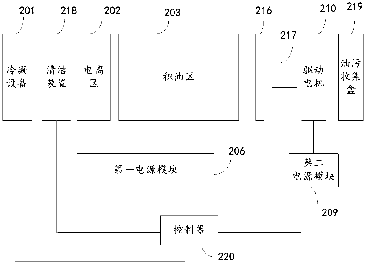
[0072] refer to image 3 , this embodiment provides an oil fume purification system, including a condensation device 201, an ionization area 202, and an oil accumulation area 203;

[0073] The ionization region 202 includes a plurality of first conductive cylinders 204 with open ends, the plurality of first conductive cylinders 204 are arranged concentrically, and a space for airflow to pass is formed between adjacent first conductive cylinders 204;

[0074] The oil accumulation area 203 includes a plurality of second conductive cylinders 205 with openings at both ends, the plurality of second conductive cylinders 205 are arranged concentrically, and a space for airflow to pass is formed between adjacent second conductive cylinders 205;

[0075] The ionization region 202 is used to form a first electric field between adjacent first conductive cylinders 204 under the action of the first voltage;

[0076] The oil accumulation area 203 is used to form a second electric field bet...


PUM


Abstract

The invention provides an oil smoke purification system. The oil smoke purification system comprises condensation equipment, an ionization region and an oil accumulation region, wherein the ionizationregion comprises a plurality of first conductive cylinders, two ends of the first conductive cylinders are opened, the plurality of first conductive cylinders are concentrically arranged, a space forairflow to pass is formed between adjacent first conductive cylinders, the oil accumulation region comprises a plurality of second conductive cylinders, two ends of the second conductive cylinders are opened, the plurality of second conductive cylinders are concentrically arranged, and a space for airflow to pass is formed between adjacent second conductive cylinders. The system is ingenious in structure design, a main body is in a cylindrical shape, the system can be conveniently arranged at a front end of an oil smoke pipeline, a front end of the oil smoke pipeline is purified, oil smoke particles are effectively prevented from being deposited in the pipeline, and the oil smoke pipeline is not needed to be cleaned; and the condensation equipment is used for cooling the system before oilsmoke purification and can be used for collecting a part of oil smoke, the cooled oil smoke is thoroughly ionized, and the oil smoke purification capability is improved.

Description

technical field [0001] The invention relates to the technical field of oil fume purification, in particular to an oil fume purification system. Background technique [0002] In the process of industrial production or cooking in the catering industry, a large amount of oily waste gas will be produced. If it is not treated and discharged directly, it will bring great pollution to the air and endanger human health. At present, the state and local governments have issued regulations on the control of oil fume pollution, requiring the catering industry to install oil fume purification equipment. [0003] Electrostatic oil fume purifier is one of the most commonly used oil fume purification equipment at present. The main working principle is: use electric field to absorb oil fume particles, let the air containing smoke, dust mist and other pollutants pass through the equipment with high-voltage electrostatic field, when the purification equipment is working , The cathode and anod...

Claims


Application Information

Patent Timeline
Patent Type & Authority Applications(China)
IPC IPC(8): B03C3/014B03C3/12B03C3/15B03C3/34B03C3/41B03C3/49B03C3/68B03C3/78
CPCB03C3/014B03C3/12B03C3/15B03C3/368B03C3/41B03C3/49B03C3/68B03C3/78
Inventor 姚新群魏玉兵
Owner 北京圣喻环保科技有限公司
Why Eureka
Try Eureka