Tracking type dynamic bottle cap marking equipment

A marking equipment and tracking technology, which is applied in welding equipment, laser welding equipment, metal processing equipment, etc., can solve the problems of time-consuming and labor-intensive loading effects, and achieve the effects of saving power, pushing materials and high precision of rotation

Active Publication Date: 2019-07-26
德玛克(长兴)注塑系统有限公司
View PDF12 Cites 1 Cited by
  • Summary
  • Abstract
  • Description
  • Claims
  • Application Information

AI Technical Summary

Problems solved by technology

[0006] Aiming at the deficiencies of the prior art, the present invention provides a tracking type dynamic bottle cap marking equipment. By setting the feeding device and the rotary device, the feeding device pushes the bottle caps that need to be coded upwards to the bottles on the rotary device. On the cap limiter, and keep track with the rotary device during the upward push process, the rotary device will drive the bottle cap on the bottle cap limiter for rotary transportation and mark it at the marking device Continue to rotate to the output component to realize the automatic outward output of the bottle cap after marking, realize the fully automatic production of the bottle cap from feeding, marking to automatic output, and solve the need to manually carry out the bottle cap in the prior art Laser marking after linear arrangement, time-consuming and labor-intensive technical problems, at the same time solves the technical problem of poor feeding effect caused by the asynchronous feeding process of bottle caps and rotary transport devices

Method used


Image

  • Tracking type dynamic bottle cap marking equipment
  • Tracking type dynamic bottle cap marking equipment
  • Tracking type dynamic bottle cap marking equipment

Examples


Embodiment 1

[0058] Embodiments of the present invention are described in detail below, examples of which are shown in the drawings, wherein the same or similar reference numerals designate the same or similar elements or elements having the same or similar functions throughout. The embodiments described below by referring to the figures are exemplary and are intended to explain the present invention and should not be construed as limiting the present invention.

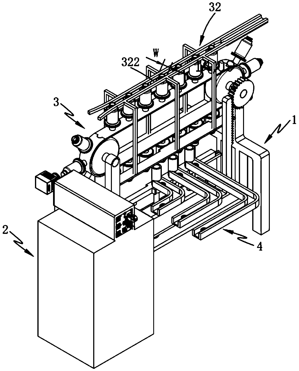
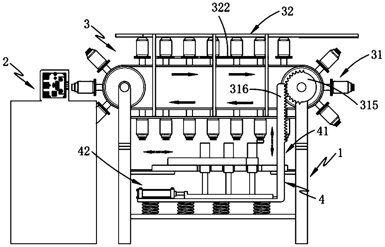
[0059] Such as figure 1 and 2 As shown, a tracking dynamic bottle cap marking equipment includes a bracket 1 and a marking device 2, and also includes:

[0060] Rotary device 3, described rotary device 3 is rotated and arranged on the two ends of the longitudinal direction of described support 1, and this rotary device 3 comprises rotary assembly 31 and is arranged on the output assembly 32 above described rotary assembly 31, and described rotary assembly 31 Transport the bottle caps 10 that need to be marked in a rotary manner...


PUM


Abstract

The invention provides tracking type dynamic bottle cap marking equipment. The tracking type dynamic bottle cap marking equipment comprises a bracket, a marking device, a rotating device and a feedingdevice, the rotating device comprises a rotating assembly and an outputting assembly, the feeding device is slidably arranged on the bracket and comprises an interval pushing assembly and a trackingassembly, and the interval pushing assembly and one end of the rotating assembly are arranged in a linkage mode; and by arranging the feeding device and the rotating device, the feeding device pushesa bottle cap needing marking upwards to a bottle cap limiting piece of the rotating device and keeps a tracking state with the rotating device in the upward pushing process, the rotating device drivesthe bottom cap located on the bottle cap limiting piece to rotate and be transported, marking processing is conducted on the bottle cap on the marking device to achieve the automatic outward output,and the problems of time and labor wasting due to the manual linear distribution of the bottle cap in the prior art and the poor feeding effect due to the asynchrony of the bottle cap and the rotatingand transporting device in the feeding process are solved simultaneously.

Description

technical field [0001] The invention relates to the technical field of bottle cap processing, in particular to a tracking type dynamic bottle cap marking equipment. Background technique [0002] In the current beverage market, it is generally used to print digital codes, character codes or simple patterns on beverage bottle caps for anti-counterfeiting and promotion, and the practical operability is relatively poor, and the establishment of a traceability system cannot be realized. At present, the technology of similar equipment adopts inkjet coding, printing, labeling, bronzing and other processes to realize the process of engraving or printing labels on the outer surface or inner surface of beverage bottle caps. [0003] Inkjet-printed patterns and QR codes cannot be in direct contact with food, as they are easy to fall off. Printing also has the problem of ink pollution, and the two-dimensional code cannot realize dynamic variable printing, that is, it cannot realize one...

Claims


Application Information

Patent Timeline
IPC IPC(8): B23K26/362B23K26/70
CPCB23K26/362B23K26/70B23K26/702
Inventor 王巍植
Owner 德玛克(长兴)注塑系统有限公司
Why Eureka
Try Eureka