Mechanical braking system of main carrier body of trailing suction carrier

A technology for mechanical braking and trolleys, applied in railway braking systems, mechanical equipment, brake types, etc., can solve the problem of inconvenience in installing and replacing friction blocks of brake devices, complex structure of connecting components of braking devices, and friction on the surface of friction blocks. Insufficient uniform force, etc., to achieve the effect of improving braking effect, easy disassembly and replacement, and uniform force

Active Publication Date: 2019-07-26
ZHONGCHUAN NO 9 DESIGN & RES INST
View PDF9 Cites 1 Cited by
  • Summary
  • Abstract
  • Description
  • Claims
  • Application Information

AI Technical Summary

Problems solved by technology

[0002] The rake suction trolley is composed of a cart (main cart) and a horizontal working trolley on it, a control system and a power supply system. The cart is composed of a frame, a control room, a driving mechanism, a horizontal guide wheel mechanism, a braking system, The speed measurement electronic control system is composed of the existing part of the braking system of the cart. The contact between the friction block and the rail is realized by rotating the friction block, and the brake is performed by friction force. Due to the rotation of the friction block, the surface of the friction block is stressed. Insufficient uniformity, resulting in insufficient braking effect of the device, and the structure of the connecting components of the braking device is relatively complicated, which is inconvenient for the installation of the braking device and the replacement of the friction block

Method used


Image

  • Mechanical braking system of main carrier body of trailing suction carrier
  • Mechanical braking system of main carrier body of trailing suction carrier
  • Mechanical braking system of main carrier body of trailing suction carrier

Examples


Embodiment Construction

[0018] The following will clearly and completely describe the technical solutions in the embodiments of the present invention with reference to the accompanying drawings in the embodiments of the present invention. Obviously, the described embodiments are only some, not all, embodiments of the present invention. Based on the embodiments of the present invention, all other embodiments obtained by persons of ordinary skill in the art without making creative efforts belong to the protection scope of the present invention.

[0019] The drawings in the embodiments of the present invention: the different types of section lines in the drawings are not marked according to the national standard, and there is no requirement for the material of the components, but to distinguish the cross-sectional views of the components in the drawings.

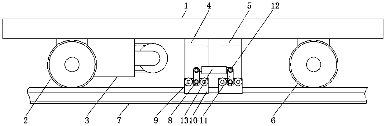
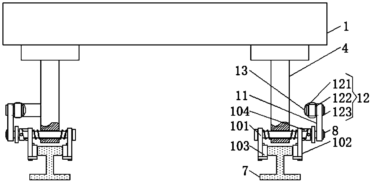
[0020] Such as figure 1 and figure 2 As shown, a mechanical braking system for a raking trolley cart includes a frame 1 and a driving wheel 2 fixed...


PUM


Abstract

The invention relates to the technical field of trailing suction carriers and discloses a mechanical braking system of a main carrier body of a trailing suction carrier. The mechanical braking systemcomprises a carrier frame and further comprises a driving wheel, a driving mechanism, a first fixing plate, a second fixing plate and a driven wheel which are sequentially and fixedly mounted at the bottom of the carrier frame from left to right. According to the mechanical braking system of the main carrier body of the trailing suction carrier, by arranging a limiting sleeve on a second connecting plate, rotation of a first rotating rod can be converted into moving through a first movable sleeve, meanwhile, rotation of second rotating rods is converted into moving through second movable sleeves while the first rotating rod enables the second rotating rods to rotate through a first gear and second gears, the main carrier body is braked through friction force between a friction block and asteel rail while a first connecting plate and the second connecting plate are closed, force bearing of the surface of the friction block is uniform through cooperative use of the second rotating rodsand the second movable sleeves, the contact area between the friction block and the steel rail is increased, and the braking effect of the mechanical braking system is improved.

Description

technical field [0001] The invention relates to the technical field of raking and suction trolleys, in particular to a mechanical braking system for a raking and suction trolley cart. Background technique [0002] The rake suction trolley is composed of a cart (main cart) and a horizontal working trolley on it, a control system and a power supply system. The cart is composed of a frame, a control room, a driving mechanism, a horizontal guide wheel mechanism, a braking system, The speed measurement electronic control system is composed of the existing part of the braking system of the cart. The contact between the friction block and the rail is realized by rotating the friction block, and the brake is performed by friction force. Due to the rotation of the friction block, the surface of the friction block is stressed. Insufficient uniformity leads to insufficient braking effect of the device, and the structure of the connecting member of the braking device is relatively compl...

Claims


Application Information

Patent Timeline
IPC IPC(8): B61H7/12F16D63/00F16D65/095
CPCB61H7/12F16D63/002F16D65/095
Inventor 慎辰张吉平蒋梦嫣汪洋吴艳青洪国军张晴波潘润道蒋明董元跃徐而敏徐剑
Owner ZHONGCHUAN NO 9 DESIGN & RES INST
Why Eureka
Try Eureka