Special vacuum cup take and place system for vacuum cup production line

A thermos cup and production line technology, applied in conveyors, mechanical conveyors, conveyor objects, etc., can solve the problems of inability to meet the needs of automated production lines, error-prone manual operations, and labor-intensive workers, to ensure conveying stability and Reliability, improve safety and reliability, save labor cost

Pending Publication Date: 2019-07-26
杭州普联自动化设备有限公司
View PDF0 Cites 3 Cited by
  • Summary
  • Abstract
  • Description
  • Claims
  • Application Information

AI Technical Summary

Problems solved by technology

[0002] During the production process of the thermos cup, it is necessary to send the thermos cup from the conveyor belt to the cup mouth processing equipment for cup mouth processing, and then take the processed thermos cup from the cup mouth processing equipment and put it back on the conveyor belt to be transported to the next process ; It is necessary to send the thermos cup from the conveyor belt to the outer wall processing equipment for processing the outer wall of the cup, and then take the processed thermos cup from the outer wall processing equipment and put it back on the conveyor belt to be transported to the next process; at present, these The process is all done manually. Manually take the thermos cup from the conveyor belt to the cup mouth processing equipment for cup mouth processing, and then take the processed thermos cup back to the conveyor belt and transport it to the next process. Not only is the production efficiency low, but The labor intensity of workers is high, and the labor cost is high; and manual operation is prone to errors, resulting in missed or repeated processing, which affects the quality of the product;
[0003] Moreover, a conveying device is usually used to transport the thermos cup between each processing equipment of the thermos cup production line. The thermos cup is transported to the discharge end, and then the thermos cup is manually picked up on the discharge end of the conveyor belt and placed on the next processing equipment for processing. Automated production line requirements for thermos cups

Method used


Image

  • Special vacuum cup take and place system for vacuum cup production line
  • Special vacuum cup take and place system for vacuum cup production line
  • Special vacuum cup take and place system for vacuum cup production line

Examples


Embodiment Construction

[0052] The present invention will be described in further detail below in conjunction with accompanying drawing, but is not the restriction to protection scope of the present invention.

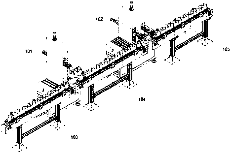
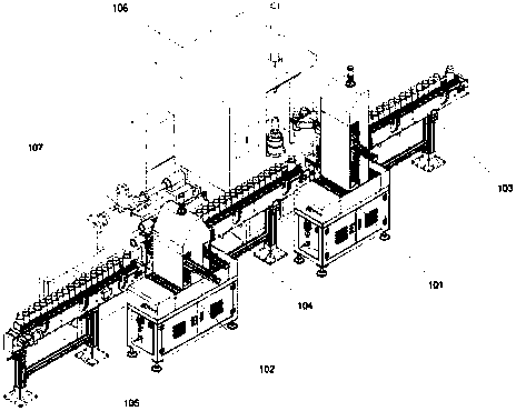
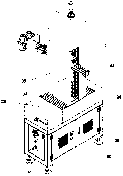
[0053] Such as Figure 1-3 As shown, a thermos cup pick-and-place system for a thermos cup production line includes a three-axis thermos cup pick-and-place device 101 that cooperates with a thermos cup mouth processing device 106, and a four-axis thermos cup pick-and-place device 102 that cooperates with a thermos cup outer wall processing device 107. , the No. 1 conveying device 103 that cooperates with the three-axis thermos cup pick-and-place device 101, the No. 2 conveyer 104 between the three-axis thermos cup pick-and-place device 101 and the surrounding thermos cup pick-and-place device 102, and the four-axis thermos cup pick-and-place device The third delivery device 105 of the device 102.

[0054] When the present invention operates, the thermos cup after the previous process is tran...


PUM


Abstract

The invention discloses a special vacuum cup take and place system for a vacuum cup production line. The special vacuum cup take and place system comprises a three-axis vacuum cup take and place device which is matched with vacuum cup mouth processing equipment, a four-axis vacuum cup take and place device which is matched with vacuum cup outer wall processing equipment as well as a conveying device I, a conveying device II and a conveying device III which are matched between the three-axis vacuum cup take and place device and the four-axis vacuum cup take and place device; the four-axis vacuum cup take and place device comprises an electrical control cabinet, a mechanical hand, a PLC and a mechanical hand protective cover; the four-axis vacuum cup take and place device comprises an electric-control cabinet, a mechanical hand, a PLC and a mechanical hand protective cover; and each of the conveying device I, the conveying device II and the conveying device III comprises a conveying bracket, a conveyor belt and a conveyor belt drive motor, the front end of the conveying bracket is equipped with a vacuum cup sucking mechanism and a vacuum cup blocking mechanism. The special vacuum cuptake and place system is high in degree of automation, is high in production efficiency, reduces labor intensity of a worker, saves labor power, is low in error rate, guarantees product quality, andis stable and reliable in conveying.

Description

technical field [0001] The invention relates to an auxiliary facility for a thermos cup production line, in particular to a thermos cup pick-and-place system for a thermos cup production line. Background technique [0002] During the production process of the thermos cup, it is necessary to send the thermos cup from the conveyor belt to the cup mouth processing equipment for cup mouth processing, and then take the processed thermos cup from the cup mouth processing equipment and put it back on the conveyor belt to be transported to the next process ; It is necessary to send the thermos cup from the conveyor belt to the outer wall processing equipment for processing the outer wall of the cup, and then take the processed thermos cup from the outer wall processing equipment and put it back on the conveyor belt to be transported to the next process; at present, these The process is all done manually. Manually take the thermos cup from the conveyor belt to the cup mouth processin...

Claims


Application Information

Patent Timeline
Patent Type & Authority Applications(China)
IPC IPC(8): B65G47/90B65G47/91B65G37/00
CPCB65G37/00B65G47/902B65G47/914B65G2201/0244
Inventor 徐浩汪大军陈自华
Owner 杭州普联自动化设备有限公司
Why Eureka
Try Eureka