Automobile hub steering knuckle automatic assembling machine and assembling method

A technology for automobile wheel hub and steering knuckle, which is applied to the automatic assembly machine and assembly field of automobile wheel hub steering knuckle, can solve the problems of low integration, unsuitable for large-scale industrial automation production, low work efficiency, etc., and achieves high integration and meets automation. Production line demand, the effect of improving support performance

Active Publication Date: 2019-03-08
YINCHUAN WEST DASEN CNC TECH
View PDF9 Cites 11 Cited by
  • Summary
  • Abstract
  • Description
  • Claims
  • Application Information

AI Technical Summary

Problems solved by technology

[0003] The assembly of the steering knuckle assembly mainly includes the press-fitting of the bearing, the clamping spring and the hub. The existing press-fitting methods are mostly manual press-fitting on a single machine, which has low integration and low work efficiency. Not suitable for large-scale industrial automation production

Method used


Image

  • Automobile hub steering knuckle automatic assembling machine and assembling method
  • Automobile hub steering knuckle automatic assembling machine and assembling method
  • Automobile hub steering knuckle automatic assembling machine and assembling method

Examples


Embodiment 1

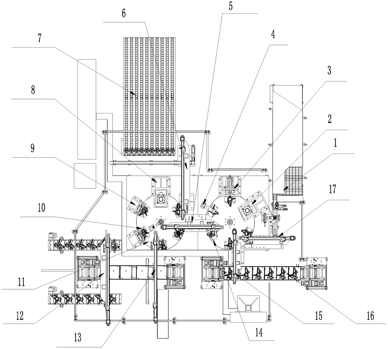
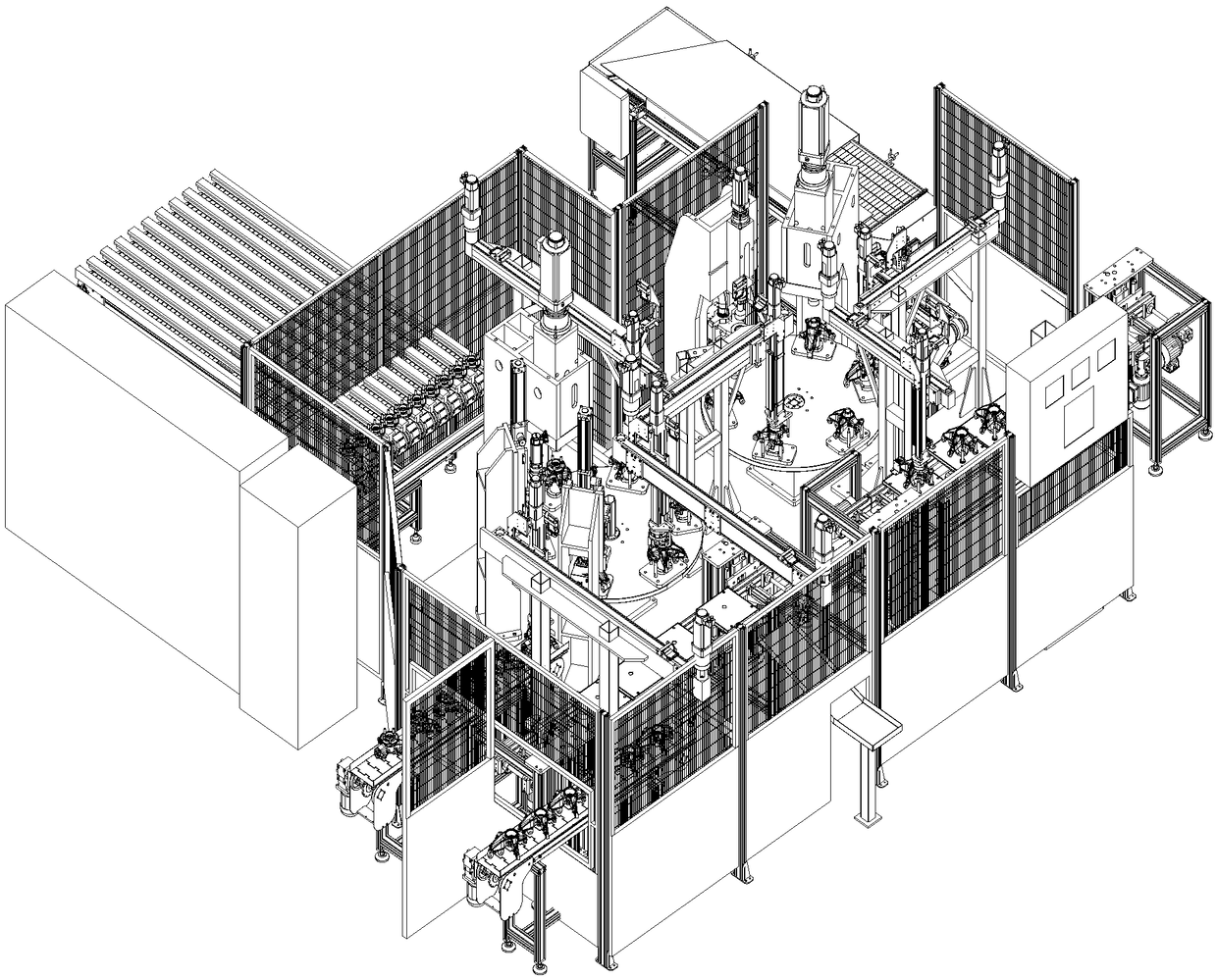
[0041] see Figure 1-11 , a kind of automobile wheel steering knuckle automatic assembly machine, comprises steering knuckle feeding conveyor line 16, and steering knuckle feeding conveyor line 16 is connected with press-fitting device 1 by steering knuckle feeding manipulator 15, and press-fitting device 1 passes bearing feeding manipulator 17 is connected to the bearing bin 1 with a conveying mechanism. The press-fitting device I completes the press-fitting and testing of the steering knuckle, bearings and circlips. The hub feeding manipulator 6 is connected to the hub material bin 7 with a conveying and stopping mechanism, and the pressing device II completes the pressing of the hub, the detection of the runout of the hub end face of the steering knuckle assembly, and the marking of the steering knuckle assembly. II is connected with finished product packaging device 12 by off-line manipulator 13.

Embodiment 2

[0043] On the basis of embodiment 1, also include:

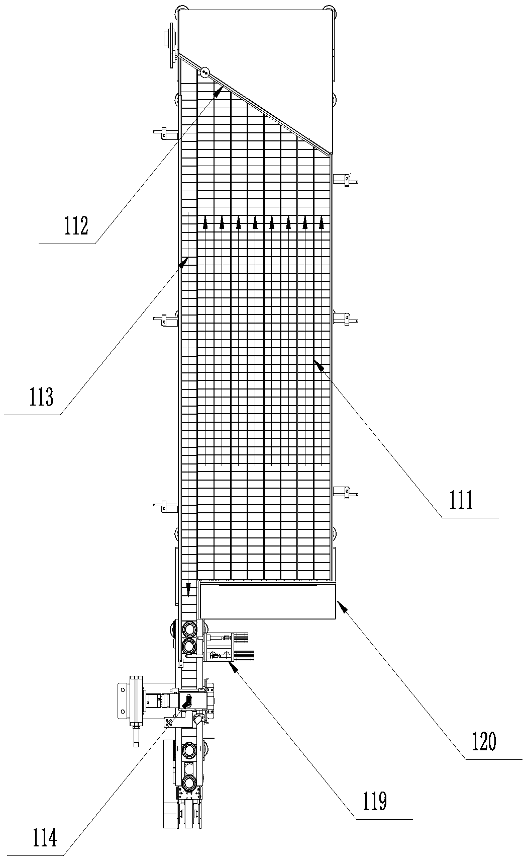
[0044] The bearing silo 1 with a conveying mechanism includes a frame I120, 8 feed conveyor lines I111 are arranged in the length direction of the frame I120, and 1 discharge conveyor line I113 is arranged side by side with the feed conveyor line I111. There is an inclined baffle 112 at the end of I111 and the front end of the discharge conveyor line I113. The baffle 112 forms an acute angle relationship with the discharge conveyor line I113. When the bearings are transported from the feed conveyor line I111 to the baffle 112, they can be removed one by one. Squeeze and push onto the discharge conveyor line I113, and the running speed of the feed conveyor line I111 is greater than that of the discharge conveyor line I113, so as to ensure timely material transportation.

[0045] The outlet end of the discharge conveying line I113 is provided with a stop mechanism I119, and the stop mechanism I119 includes a stop cylinder I, w...

Embodiment 3

[0049] On the basis of embodiment 1, also include:

[0050] Press-fitting device 1 comprises rotary table I14, and described rotary table I14 is respectively provided with bearing press machine 2, jumper spring feeding press-loader 3 and jumper spring detection machine 4 (rotary table I14, bearing presser 2, jumper ring upper circle) The material pressing machine 3 and the snap ring detection machine 4 all adopt the molding equipment of the prior art, and will not be described here). The lower part of the rotary table 1 is facing the bearing press machine 2 and the spring feeding press machine 3. There is a slope self-locking support mechanism (due to the angle of view in the figure 1 not shown in ).

[0051] The press-fitting device II includes a rotary table II11, and the rotary table II11 is respectively equipped with a hub press-fitting machine 8, a steering knuckle assembly hub end face runout detection machine 9 and a steering knuckle assembly marking machine 10 (rotary...


PUM


Abstract

The invention discloses an automobile hub steering knuckle automatic assembling machine. The automatic assembling machine comprises a steering knuckle feeding conveying line, the steering knuckle feeding conveying line is connected with a pressing device I through a steering knuckle feeding mechanical arm, the pressing device I is connected with a bearing stock bin with a conveying mechanism through a bearing feeding mechanical arm, a steering knuckle, a bearing and a clamp spring are pressed and detected in the pressing device I, the pressing device I is connected with a pressing device II through a conveying mechanical arm, the pressing device II is connected with a hub stock bin with a conveying and stopping mechanism through a hub feeding mechanical arm, the hub pressing, the steeringknuckle assembly hub end surface run-out detection and the steering knuckle assembly marking are completed in the pressing device II, and the pressing device II is connected with a finished product packaging device through a discharging mechanical arm. The assembling machine is high in the integration degree, can carry out assembly line type bearing pressing, the clamp spring pressing and the hubpressing, and meets the requirements of industrial and automatic production.

Description

technical field [0001] The invention relates to the assembly of a steering knuckle assembly, in particular to an automatic assembly machine and an assembly method for an automobile hub steering knuckle. Background technique [0002] The steering knuckle is one of the important parts in the steering axle of the car, which can make the car run stably and transmit the driving direction sensitively. The function of the steering knuckle is to transmit and bear the load on the front of the car, support and drive the front wheel to rotate around the kingpin to make the car turn . [0003] The assembly of the steering knuckle assembly mainly includes the press-fitting of the bearing, the clamping spring and the wheel hub. The existing press-fitting methods are mostly manual press-fitting on a single machine, which has low integration and low work efficiency. Not suitable for large-scale industrial automation production. Contents of the invention [0004] The purpose of the prese...

Claims


Application Information

Patent Timeline
Patent Type & Authority Applications(China)
IPC IPC(8): B23P21/00
CPCB23P21/004B23P21/006
Inventor 潘相昇
Owner YINCHUAN WEST DASEN CNC TECH
Why Eureka
Try Eureka