Optical module and optoelectronic demodulation module for fluorescence optical fiber temperature-control system

An optical module and temperature control system technology, applied in the coupling of optics, optical components, optical waveguides, etc., can solve problems such as affecting the efficiency and accuracy of fluorescent fiber temperature measurement, impurity blocking the optical path transmission of the module, and optical signals failing to transmit normally. Achieve the effect of improving temperature measurement efficiency and temperature measurement accuracy, improving reliability and stability, and simple structure

Pending Publication Date: 2019-07-26
西安和其光电科技股份有限公司
View PDF0 Cites 2 Cited by
  • Summary
  • Abstract
  • Description
  • Claims
  • Application Information

AI Technical Summary

Problems solved by technology

[0004] In order to solve the problem that the existing photoelectric demodulation module is easy to enter impurities, and the accumulation of impurities for a long time hinders the transmission of the optical path inside the module, m

Method used


Image

  • Optical module and optoelectronic demodulation module for fluorescence optical fiber temperature-control system
  • Optical module and optoelectronic demodulation module for fluorescence optical fiber temperature-control system
  • Optical module and optoelectronic demodulation module for fluorescence optical fiber temperature-control system

Examples


Example Embodiment

[0039] The present invention will be further described in detail below with reference to the drawings and embodiments.

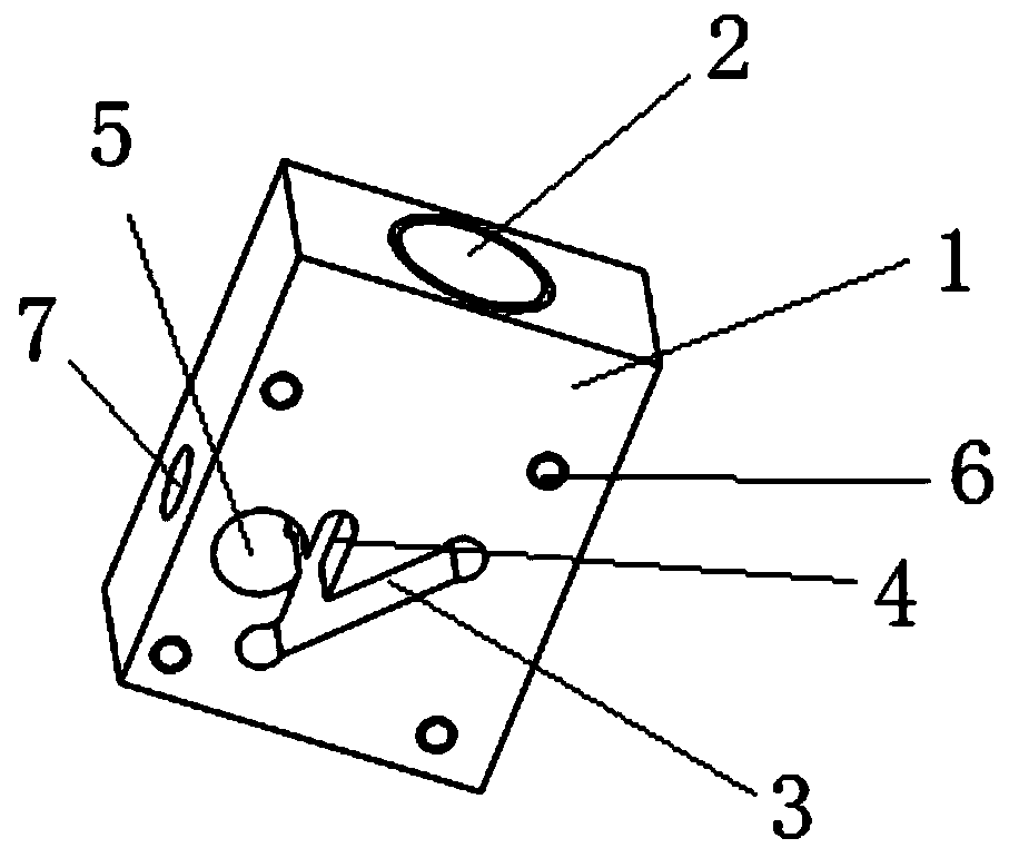
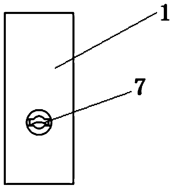
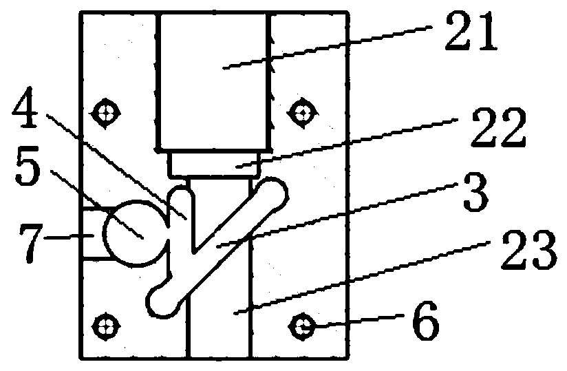
[0040] Such as Figure 1 to 5 As shown, an optical module for a fluorescent optical fiber temperature control system includes a mounting base 1 and a light emitting diode 81, a lens 82, an optical fiber connector 83, a first filter 84, and a second filter 85 arranged in the mounting base. The material of the mounting seat is aluminum alloy; the front surface of the mounting seat is provided with three stepped through holes 2 penetrating through the rear surface, which are respectively the first through hole 21, the second through hole 22 and the third through hole 23 with decreasing diameters. , The first through hole 21 is provided with a thread; one end of the optical fiber connector 83 is installed in the first through hole 21, one end of the lens 82 is installed in the second through hole 22, and the light emitting diode 81 is installed in the third through ...


PUM


Abstract

The invention provides an optical module and an optoelectronic demodulation module for a fluorescence optical fiber temperature-control system. The problem that impurities easily enter an existing optoelectronic demodulation module, consequently, the fluorescence optical fiber temperature-measuring efficiency and precision are affected is solved. The optical module comprises a mounting seat and further comprises a light-emitting diode, a lens, an optical fiber connector, a first filter and a second filter which are arranged in the mounting seat; three layers of step through holes penetrating through the rear surface are formed in the front surface of the mounting seat, and the three layers of step through holes are the first through hole, the second through hole and the third through hole,wherein the diameters of the first through hole, the second through hole and the third through hole are sequentially decreased; one end of the optical fiber connector is mounted in the first throughhole, one end of the lens is mounted in the second through hole, and the light-emitting diode is mounted in the third through hole; a first strip-shaped hole, a second strip-shaped hole and a fourth through hole which penetrate through the lower surface and communicate with one another are formed in the upper surface of the mounting seat; the first filter is mounted in the first strip-shaped hole,the second filter is mounted in the second strip-shaped hole, the fourth through hole is used for mounting of a PD, and the second filter is located between the first filter and the PD.

Description

technical field [0001] The invention belongs to the field of fluorescent optical fiber temperature control, in particular to an optical module and a photoelectric demodulation module used in a fluorescent optical fiber temperature control system. Background technique [0002] At present, the fluorescent optical fiber temperature control system is composed of a temperature demodulator, a penetrator, and an optical fiber of a temperature measuring probe containing a rare earth fluorescent substance. One end of the rare earth fluorescent substance. One end of both ends of the optical fiber is connected to the temperature demodulator, and the other end including the temperature measuring probe is placed at the measured point. The excitation light source in the temperature demodulator excites the phosphor in the probe through optical fiber transmission. At different temperatures, the phosphor emits different optical signals back to the demodulator, and then demodulates the emitt...

Claims


Application Information

Patent Timeline
IPC IPC(8): G01K11/32G02B6/42
CPCG01K11/32G02B6/4251
Inventor 张文松陈九歌朱香平
Owner 西安和其光电科技股份有限公司
Why Eureka
Try Eureka