Waste rubber crawler belt steel wire cutter mechanism

A technology for scrap rubber and cutter, applied in the field of scrap rubber crawler steel wire cutter mechanism, can solve the problems of too long tie wire and difficult collection of steel wire, etc.

Pending Publication Date: 2019-07-30
ZHENJIANG SHEN WARD MACHINERY CO LTD
View PDF0 Cites 2 Cited by
  • Summary
  • Abstract
  • Description
  • Claims
  • Application Information

AI Technical Summary

Problems solved by technology

The existing waste rubber material recovery device is not specially equipped with a cutting device for the tie wire, resulting in the tie wire being too long and coiled, making it difficult to collect the wire

Method used


Image

  • Waste rubber crawler belt steel wire cutter mechanism
  • Waste rubber crawler belt steel wire cutter mechanism
  • Waste rubber crawler belt steel wire cutter mechanism

Examples


Embodiment 1

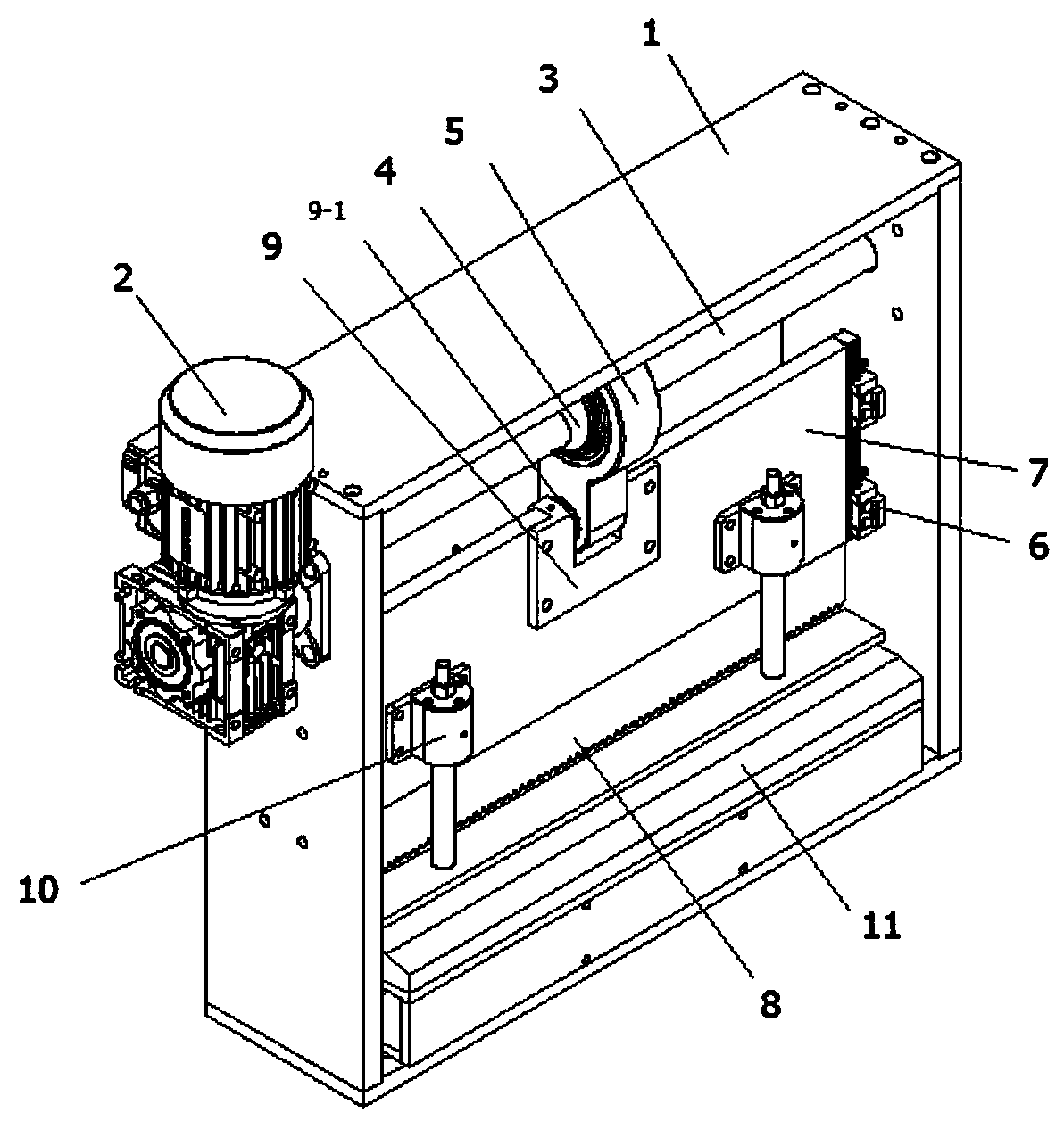
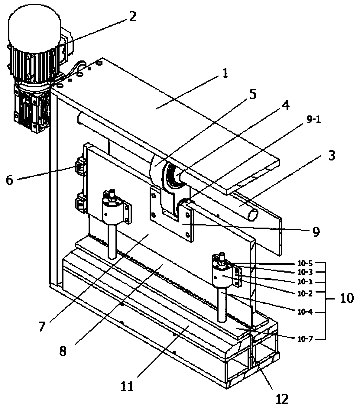
[0028] Attached Figure 1-3 It can be seen that a scrap rubber crawler wire cutter mechanism includes a cutter frame, a drive motor, a drive shaft, an eccentric cam, a connecting block, a clamping block, an upper tool holder, an upper cutter, a clamping piece, a lower pressing structure, The lower knife holder, the lower knife; the drive motor is arranged at the top end of one side of the knife frame, and the drive motor is fixedly connected to the knife frame by a fastener; the drive shaft is arranged on the At the top end of the cutter frame, both ends of the drive shaft and both sides of the cutter frame are rotated by bearings, and one end of the drive shaft extends out of the cutter frame and is fixedly connected to one end of the drive motor; The eccentric cam is arranged on the drive shaft, the eccentric cam is arranged eccentrically with the drive shaft, both sides of the eccentric cam are fixedly connected with the drive shaft; the upper cutter is arranged on the bottom...

Embodiment 2

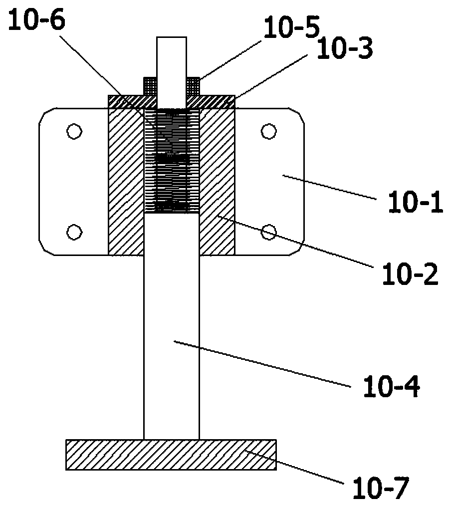
[0043] Attached Figure 4-5 It can be seen that the difference between the second embodiment and the first embodiment is the down-pressing structure. The down-pressing structure includes a fixing piece, a resisting plate, a limit cylinder, a down pressure rod, a down rod protrusion, and a limit spring. The abutment plate is arranged on one side of the fixing plate and is fixedly connected to the fixing plate; the limiting cylinder is arranged on the top surface of the fixing plate, and is fixedly connected to the abutment plate in a through arrangement; The pressing rod is arranged in the limiting cylinder; the lower pressing rod protrusion is arranged at the top end of the lower pressing rod and is fixedly connected with the lower pressing rod; the limiting spring is arranged on the outer side wall of the limiting cylinder , The top end of the limit spring is fixedly connected to the bottom surface of the lower pressing rod convex block, and the bottom end of the limit spring ...


PUM


Abstract

The invention discloses a waste rubber crawler belt steel wire cutter mechanism. The mechanism comprises a cutter frame body, a driving motor, a driving shaft, an eccentric cam, a connecting block, clamping blocks, an upper cutter rest, an upper cutter, a clamping piece, lower pressing structures, lower cutter rests and a lower cutter, the driving motor is arranged at the top end of one side of the cutter frame body, one end of the driving shaft is fixedly connected with the driving motor, the eccentric cam is eccentrically arranged with the driving shaft, the upper cutter is arranged at the bottom end of the upper cutter rest, the clamping block is fixedly connected with the cutter frame body through a fastener, the upper cutter rest is in sliding connection with the clamping block, the clamping piece is arranged at the center of the top end of the upper cutter rest, the eccentric cam is connected with the upper cutter rest through the connecting block, the lower pressing structures are arranged on the two sides of the upper cutter rest, and the lower cutter is fixedly connected with the lower cutter rest. The crawler belt wires are processed in a centralized mode, the waste collecting difficulty is reduced, the working safety of the mechanism is high, and the processing efficiency is high.

Description

Technical field [0001] The invention relates to the field of waste rubber recycling, in particular to a scrap rubber track steel wire cutter mechanism. Background technique [0002] The track is composed of track shoes and track pins. The track pins connect the track shoes to form a track chain link. There are holes on both ends of the track shoe to mesh with the driving wheel, and there are induced teeth in the middle to correct the track and prevent the track from falling off when turning or tilting. There are reinforced anti-skid ribs (referred to as pattern) on the side that contacts the ground. To improve the firmness of the track shoe and the adhesion between the track and the ground. According to the classification of raw materials, the crawler can be divided into rubber crawler and steel crawler. Among them, the rubber crawler chassis is mostly suitable for small light industry and small construction machinery industry. Light industry is generally agricultural machiner...

Claims


Application Information

Patent Timeline
Patent Type & Authority Applications(China)
IPC IPC(8): B21F11/00
CPCB21F11/00
Inventor 俞世顺沈秀昌陈友朱雪梅
Owner ZHENJIANG SHEN WARD MACHINERY CO LTD
Why Eureka
Try Eureka