A Denture Automatic Grinding Control System

A control system and denture technology, applied in the field of automatic denture grinding control system, can solve the problems of low grinding degree and different standards, and achieve the effects of high processing efficiency, pollution prevention and tight coordination

Inactive Publication Date: 2020-03-27
四川天府珞埔科技有限公司
View PDF1 Cites 0 Cited by
  • Summary
  • Abstract
  • Description
  • Claims
  • Application Information

AI Technical Summary

Problems solved by technology

Use automation to perform high-precision grinding on batches of dentures, solve the problem of over-polishing or under-polishing, improve the grinding efficiency, and solve the problems of low efficiency and inconsistent standards that rely on manual subjective judgment of the degree of grinding in the traditional method

Method used


Image

  • A Denture Automatic Grinding Control System
  • A Denture Automatic Grinding Control System
  • A Denture Automatic Grinding Control System

Examples


Embodiment 1

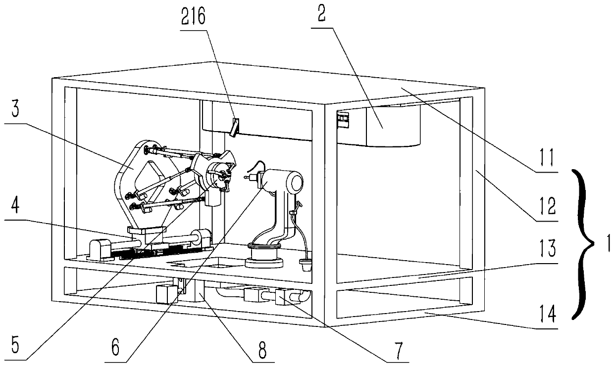
[0057] Such as figure 1 As shown, this embodiment discloses an automatic denture grinding control system, which includes a controller (not shown), a frame support device 1, an automatic denture transmission device 2, a parallel arm platform device 3, a longitudinal translation device 4, Denture automatic clamping device 5, series mechanical arm device 6, denture collection device 8 and polishing fluid circulation device 7; said denture automatic transmission device 2, longitudinal translation device 4, series mechanical arm device 6, denture collection device 8 and polishing fluid The circulation device 7 is installed on the frame support device 1; the parallel arm platform device 3 is arranged on the longitudinal translation device 4, and the denture automatic clamping device 5 is arranged at the end of the parallel arm platform device 3; the longitudinal translation device 4 can be installed on the machine The frame support device 1 moves longitudinally, the parallel arm pla...

Embodiment 2

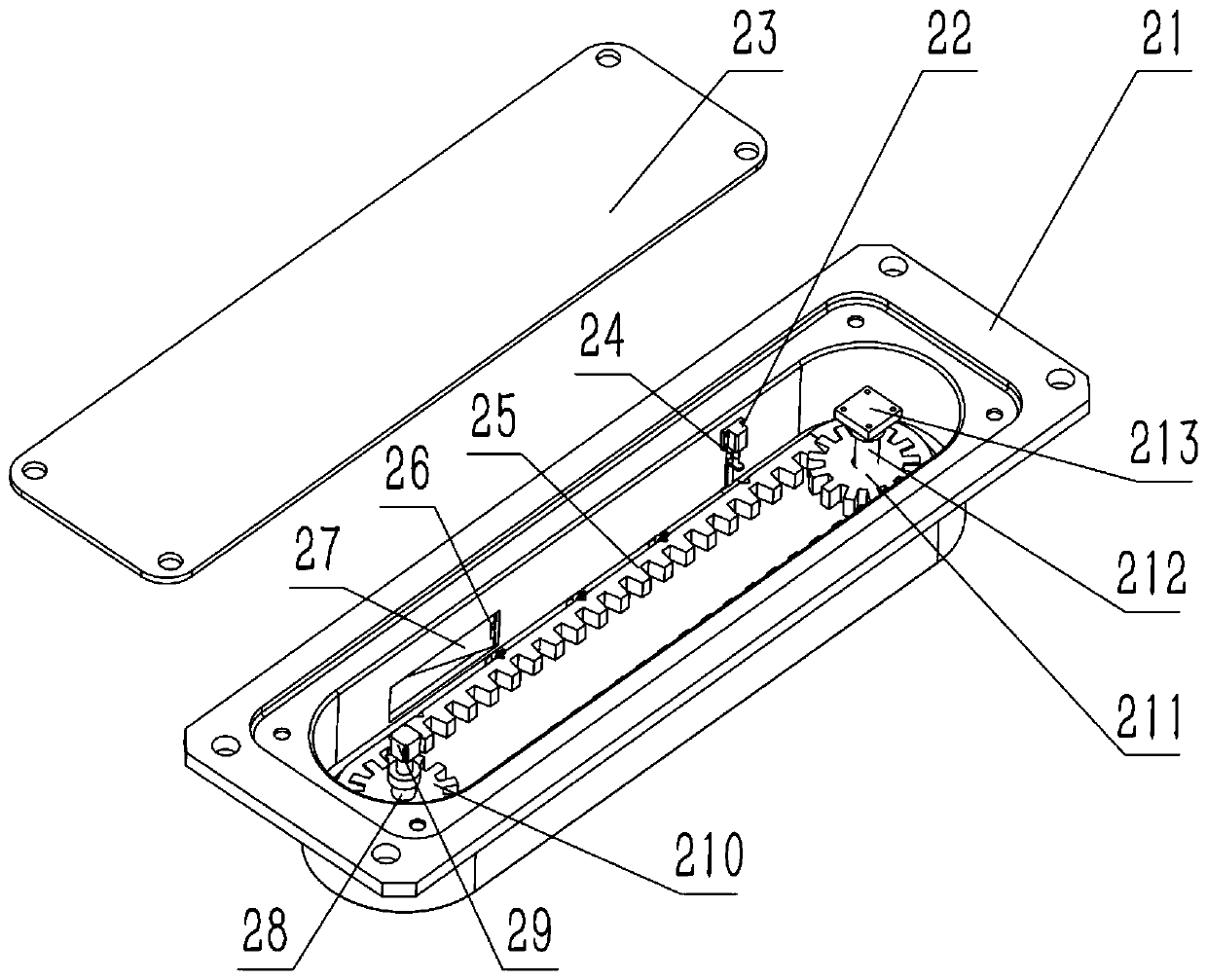
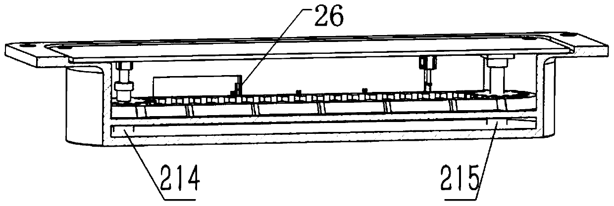
[0072] This embodiment discloses the structure of the above-mentioned automatic denture transmission device 2 . It includes a shell and a top plate that match each other. The shell is designed in a concave shape. The top plate is set at the opening of the shell, and forms a cavity when it is docked with the shell; in the cavity, a transmission mechanism is provided, and a denture bearing mechanism is designed on the transmission mechanism. The denture The carrying mechanism can carry several dentures and separate each denture; on the side of the shell, there are respectively a feeding port and a discharging port, the feeding port exposes the denture carrying mechanism, and the discharging port is flush with the denture carrying mechanism; A first gate control mechanism is provided at the discharge port, and the first gate control mechanism can open or close the discharge port; the transmission mechanism and the first gate control mechanism are respectively connected to the cont...

Embodiment 3

[0076] This embodiment discloses the structure of the above-mentioned parallel arm platform device 3 . It includes a first flat plate, a second flat plate and three pairs of push rod systems arranged between them; the first flat plate is used to install the denture automatic clamping device 5, and the second flat plate is fixed on the longitudinal translation device; each group of push rods The rod systems each include a first universal hinge 33 , a first hinge seat 32 , a servo motor 36 , a sleeve 35 , a push rod 34 , a second universal hinge 38 and a second hinge seat. The first hinge seat 32 is fixed on the first flat plate, one end of the first universal hinge 33 is connected to the first hinge seat 32, and the other end is connected to one end of the push rod 34, and the other end of the push rod 34 is sleeved in the sleeve 35, and Can slide in the sleeve 35, the bottom end of the sleeve 35 is connected with one end of the second hinge, the other end of the second hinge i...


PUM


Abstract

The invention discloses an automatic denture grinding control system. The system comprises a frame supporting device and an automatic denture transmission device arranged on it, a parallel arm platform device, a longitudinal translation device, an automatic denture clamping device, a series mechanical arm device, a denture The collection device and the polishing fluid circulation device are connected with the controller respectively to the denture automatic transmission device, the parallel arm platform device, the longitudinal translation device, the denture automatic clamping device, the series mechanical arm device, the denture collection device and the polishing fluid circulation device. Through the above system, batch transmission, positioning, posture adjustment, clamping, high-precision grinding and collection of dentures can be realized. This system has high efficiency in grinding dentures and can grind dentures in batches.

Description

technical field [0001] The invention relates to the field of denture grinding, in particular to an automatic denture grinding control system. Background technique [0002] As an important part of oral implant technology, dentures are usually manufactured through the steps of denture filling, molding and polishing in the early stage. With the continuous innovation of 3D printing technology, it has been widely used in denture production. Now through 3D printing, tooth bases, crowns, bridges, crowns, veneers, inlays, etc. can be printed, and high-precision printing of corresponding complex structures can be achieved. Currently, the main technical forms of 3D printing include Selective Lasersintering (SLS), Stereolithography Appearance (SLA), Laminated Object Manufacturing (LOM), and Fused Deposition Modeling (FDM). And inkjet printing technology, but no matter what processing method is used to produce dentures, the process of grinding and polishing needs to be completed before...

Claims


Application Information

Patent Timeline
Patent Type & Authority Patents(China)
IPC IPC(8): B24B19/00B24B41/06B24B57/02B24B51/00B24B41/00
CPCB24B19/00B24B41/005B24B41/06B24B51/00B24B57/02
Inventor 杨加兴
Owner 四川天府珞埔科技有限公司
Why Eureka
Try Eureka