
High-efficiency slitting machine for mixing rubber

A rubber mixing and cutting machine technology, which is applied in metal processing and other directions, can solve the problems of affecting the cutting quality of mixing rubber, easy position deviation, cutting error of cutting knife, etc., and achieves convenient adjustment, safe and convenient use, The effect of firm installation

Inactive Publication Date: 2019-07-30
浙江柏冠精密机械制造有限公司
View PDF1 Cites 6 Cited by
  • Summary
  • Abstract
  • Description
  • Claims
  • Application Information

AI Technical Summary

Problems solved by technology

[0003] The purpose of the present invention is to provide a high-efficiency slicer for rubber mixing, to solve the problem that the existing rubber slicer in the above-mentioned background technology cannot meet the production requirements of actual mixing rubber slices. The distance between the blades is adjusted and fixed, the adjustment of the cutting knife is troublesome, the installation is not firm, and the position of the mixed rubber is easy to shift when the material is conveyed, resulting in errors in the cutting of the cutting knife and affecting the cutting quality of the mixed rubber.

Method used


Image

  • High-efficiency slitting machine for mixing rubber
  • High-efficiency slitting machine for mixing rubber
  • High-efficiency slitting machine for mixing rubber

Examples


Embodiment Construction

[0019] The technical solutions in the embodiments of the present invention will be clearly and completely described below in conjunction with the accompanying drawings in the embodiments of the present invention. Obviously, the described embodiments are only some of the embodiments of the present invention, not all of them. Based on The embodiments of the present invention and all other embodiments obtained by persons of ordinary skill in the art without making creative efforts belong to the protection scope of the present invention.

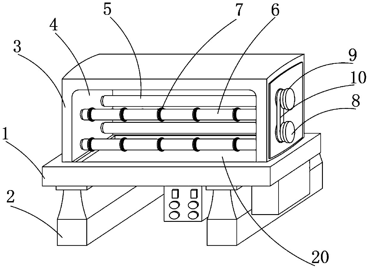
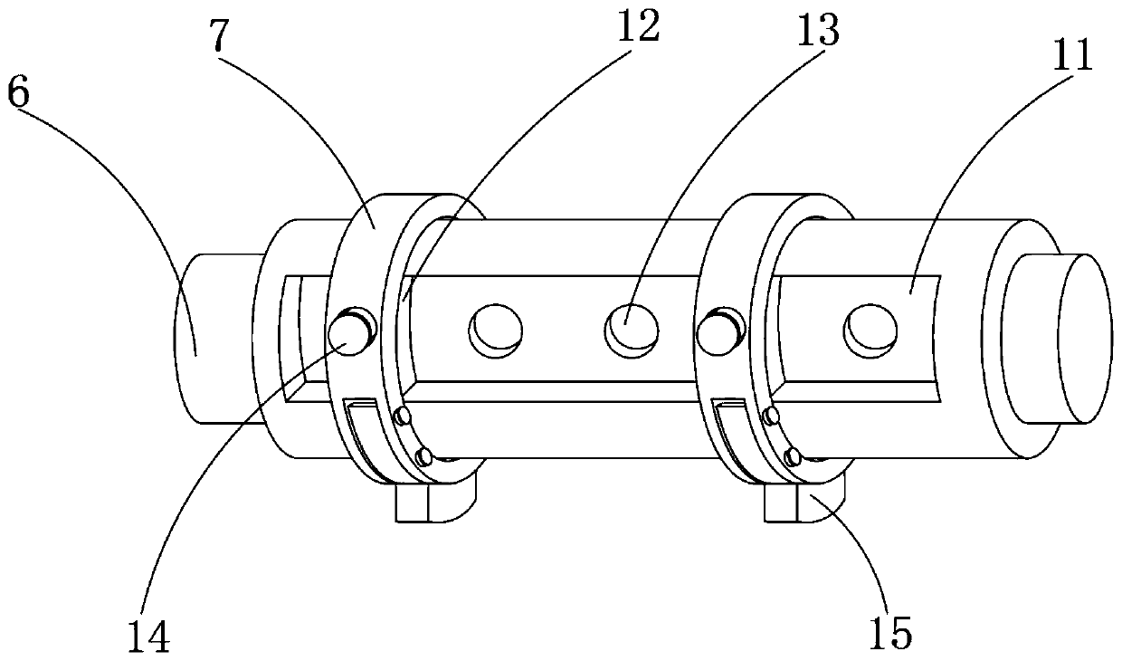
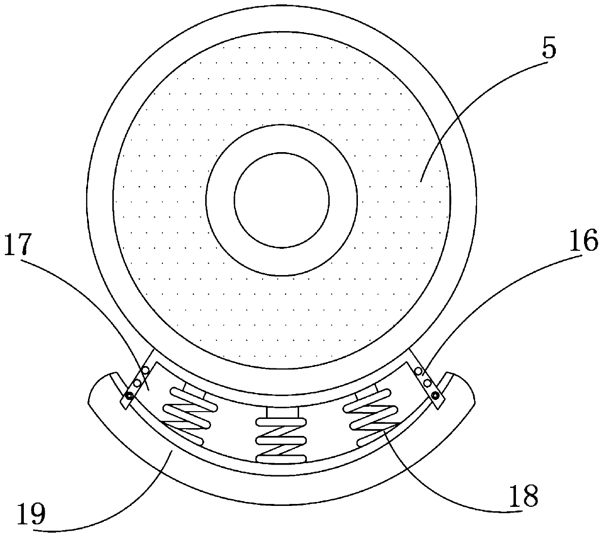
[0020] see Figure 1-4 , the present invention provides a technical solution, a high-efficiency splitting machine for rubber mixing, including a fixed table 1, and support feet 2 are installed on both sides of the bottom of the fixed table 1, and the top of the fixed table 1 is installed with a fixed nut The film opening support 3, the film opening support 3 is provided with a film opening chamber 4, one side of the film opening chamber 4 inner ...


PUM


Abstract

The invention discloses a high-efficiency slitting machine for mixing rubber. The high-efficiency slitting machine comprises a fixing table; a slitting bracket is arranged at the top end of the fixingtable; pressing rollers are arranged on one side in the slitting bracket; direction adjusting rollers are arranged on one sides of the pressing rollers; sliding grooves are formed in the direction adjusting rollers; silica gel gaskets are mounted at the bottom ends of the pressing rollers through fixing rods; and collecting grooves are formed in the middle of the fixing table. The high-efficiencyslitting machine is scientific and reasonable in structure and safe and convenient to use; with the arrangement of the direction adjusting rollers and the sliding grooves, the slitting machine can conveniently adjust and fix the spacing between splitting cutters inside the guide rollers according to the actual production requirements of the mixing rubber; with the arrangement of the fixing rods and silica gel backing plates, the problem that the cutting quality of mixing rubber is affected since the position of the mixing rubber is easy to shift during material conveying is solved; and with the arrangement of the collecting grooves, the cleanliness of an internal environment of the slitting machine is ensured, and dust and impurities are prevented from falling into the slitting machine tocause a failure of the slitting machine.

Description

technical field [0001] The invention relates to the technical field of rubber splitters, in particular to a high-efficiency splitter for mixing rubber. Background technique [0002] The slicing machine is an important machine in the rubber industry. It is mainly used for rubber pressing and sheeting. In the prior art, there are a lot of disclosures about the structure of the rubber slicing machine. Among them (patent publication number CN 206982794U) the rubber The splitting machine is convenient to keep the rubber material dry, so that the quality of the processed rubber is stable, but this patent cannot adjust and fix the distance between the splitting knives inside the guide roller according to the actual production needs of mixing rubber splitting. It is troublesome to adjust, the installation is poor, and the position of the mixed rubber is easy to shift when it is conveyed, which leads to the error of the cutting knife and affects the cutting quality of the mixed rubbe...

Claims


Application Information

Patent Timeline
Patent Type & Authority Applications(China)
IPC IPC(8): B29B7/52B29B7/58B26D1/25B26D7/26
CPCB26D1/255B26D7/2628B29B7/52B29B7/58
Inventor 郑丽珠陈良松
Owner 浙江柏冠精密机械制造有限公司
Learn More