
Self-cleaning type rotary valve for wellhead of oil pumping unit

A self-cleaning technology for pumping wells, which is applied to valve details, valve devices, and valve casing structures, can solve the problem of dust and dirt, insufficient utilization of extra space outside the valve body, discounts on valve body performance and practicability, etc. problems, to achieve the effect of improving the performance of the assembly

Inactive Publication Date: 2019-07-30
兰新伟
View PDF0 Cites 0 Cited by
  • Summary
  • Abstract
  • Description
  • Claims
  • Application Information

AI Technical Summary

Problems solved by technology

[0004] The purpose of the present invention is to provide a self-cleaning pumping unit wellhead rotary valve to solve the problem that the existing valve structure design and its simplicity in the above-mentioned background technology, the extra space outside the valve body and its structure are not fully utilized, resulting in The performance and practicability of the valve body are greatly reduced, and the valve body will generally produce more dust and dirt due to long-term practical use, and it is easy to breed more germs. Since the valve body is not equipped with a self-cleaning mechanism, resulting in the valve body is not safe to use

Method used

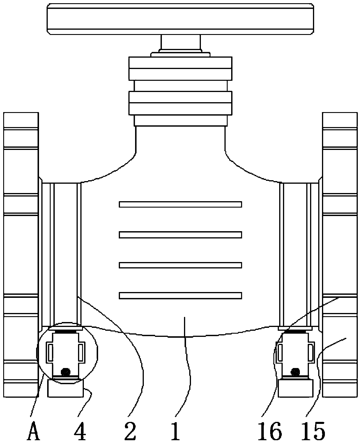

Image

  • Self-cleaning type rotary valve for wellhead of oil pumping unit
  • Self-cleaning type rotary valve for wellhead of oil pumping unit
  • Self-cleaning type rotary valve for wellhead of oil pumping unit

Examples


Embodiment Construction

[0026] The following will clearly and completely describe the technical solutions in the embodiments of the present invention with reference to the accompanying drawings in the embodiments of the present invention. Obviously, the described embodiments are only some, not all, embodiments of the present invention.

[0027] In the description of the present invention, unless otherwise stated, the meaning of "plurality" is two or more; the terms "upper", "lower", "left", "right", "inner", "outer" , "front end", "rear end", "head", "tail", etc. indicate the orientation or positional relationship based on the orientation or positional relationship shown in the drawings, and are only for the convenience of describing the present invention and simplifying the description, rather than Nothing indicating or implying that a referenced device or element must have a particular orientation, be constructed, and operate in a particular orientation should therefore not be construed as limiting ...


PUM


Abstract

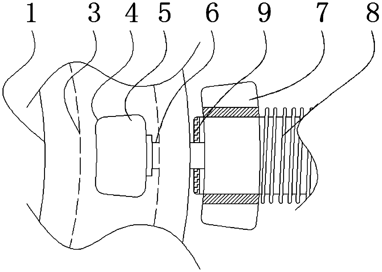
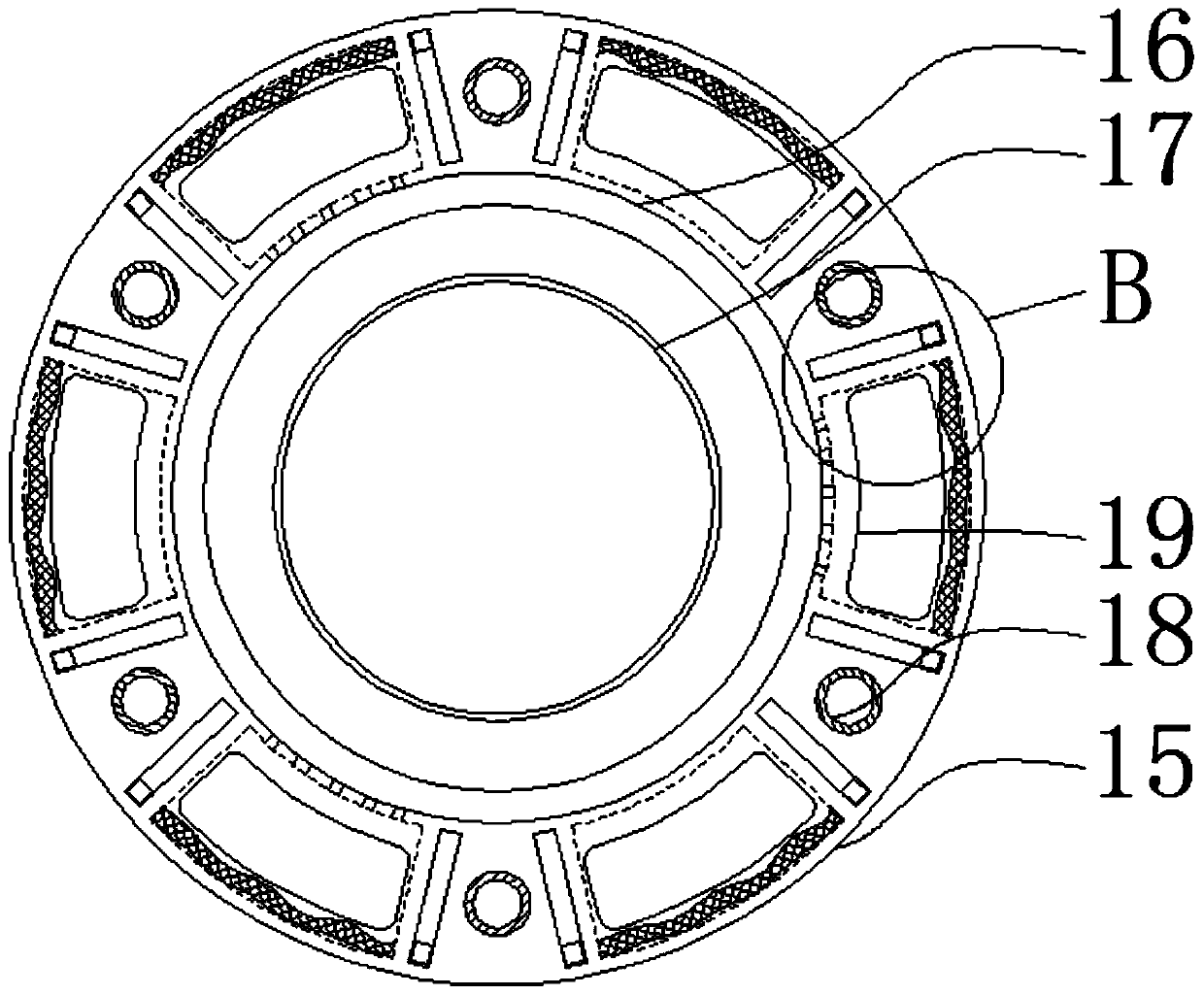
The invention relates to a self-cleaning type rotary valve for a wellhead of an oil pumping unit. The self-cleaning type rotary valve comprises a valve body and connecting side bases, wherein outer walls of left and right ends of the valve body are equipped with jointing slide paths; inner ends of the jointing slide paths are connected with slide slots; the inner ends of the slide slots are jointed with linking mechanisms; the connecting side bases are positioned outside left and right ends of the valve body; and ring-shaped sealing rings are arranged at the inner sides of the connecting sidebases. The self-cleaning type rotary valve has the beneficial effects that: the self-cleaning type rotary valve for the wellhead of the oil pumping unit is equipped with side strip handles and positioning screws, and can be conveniently held through the side strip handles, so that a jointing middle column is conveniently controlled to use; and meanwhile, through rotary use of the positioning screw, positioning operation can be performed on the jointing middle column through fitting, so that thread connecting operation can be conveniently performed through a threaded connecting hole, and therefore, a fixed blocking base is conveniently in threaded connection and fixation to outside fixing substances to achieve multiple positioning effects, and assembly performance of the device body is conveniently improved.

Description

technical field [0001] The invention relates to the technical field of oil well exploitation, in particular to a self-cleaning well head rotary valve of a pumping unit. Background technique [0002] In order to extract oil, the holes drilled according to the well layout system of the oil field development plan, the passage of oil rising from the bottom of the well to the well head, and the oil well is the hole drilled by the drilling method. Generally, after the oil well is drilled into the oil layer, the oil layer casing is lowered, and oil well cement is injected into the annular space between the casing and the well wall. At the same time, valves are generally used to control transportation during oil well production. [0003] The existing valve structure design is extremely simple, and the excess space outside the valve body and its structure are not fully utilized, which leads to a great reduction in the performance and practicability of the valve body, and the valve bo...

Claims


Application Information

Patent Timeline
Patent Type & Authority Applications(China)
IPC IPC(8): F16K27/00F16K51/00F16L23/032F16L23/18
CPCF16K27/00F16K51/00F16L23/032F16L23/18
Inventor 兰新伟
Owner 兰新伟
Learn More