
Shield tunneling machine tool batch experiment mechanism

A shield machine tool and batch technology, applied in the field of shield machines, can solve problems such as long time spent, no protective equipment, soil layer slipping, etc., and achieve the effects of avoiding wasting time, improving efficiency, and facilitating disassembly and installation

Active Publication Date: 2019-07-30
马鞍山灵山机械设备科技有限公司
View PDF9 Cites 2 Cited by
  • Summary
  • Abstract
  • Description
  • Claims
  • Application Information

AI Technical Summary

Problems solved by technology

[0003] Before using the shield machine tool in the prior art, a series of simulation experiments are required to observe its specific wear condition before it is officially put into use. There are some problems in the traditional shield machine simulation experiment. When the experiment is carried out, the simulation The soil layer needs to be filled into the simulation frame, and then it needs to be settled for a certain period of time, so that the soil layer is closer to the real soil layer. However, in the prior art, it is generally only a single operation, which leads to low efficiency when simulating tools in batches. Low, it takes a long time. In addition, in the filling process, because the traditional filling method is to add directly on the simulation frame without any protective equipment, it is easy to cause the soil layer to slip. For this reason, we provide a shield Mechanism tool batch experiment mechanism to solve some problems in the above background technology

Method used


Image

  • Shield tunneling machine tool batch experiment mechanism
  • Shield tunneling machine tool batch experiment mechanism
  • Shield tunneling machine tool batch experiment mechanism

Examples


Embodiment Construction

[0025] The following will clearly and completely describe the technical solutions in the embodiments of the present invention with reference to the accompanying drawings in the embodiments of the present invention. Obviously, the described embodiments are only some, not all, embodiments of the present invention. Based on the embodiments of the present invention, all other embodiments obtained by persons of ordinary skill in the art without creative efforts fall within the protection scope of the present invention.

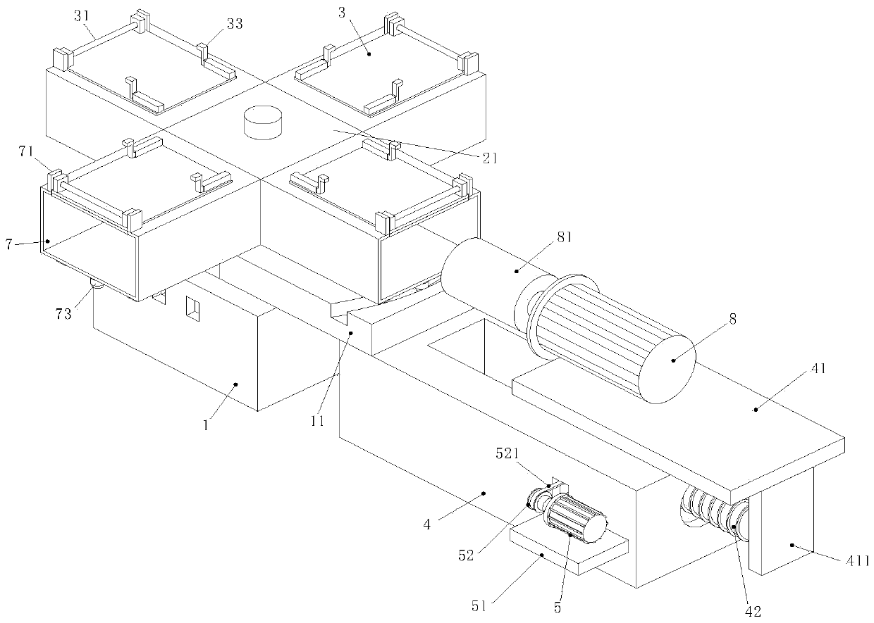
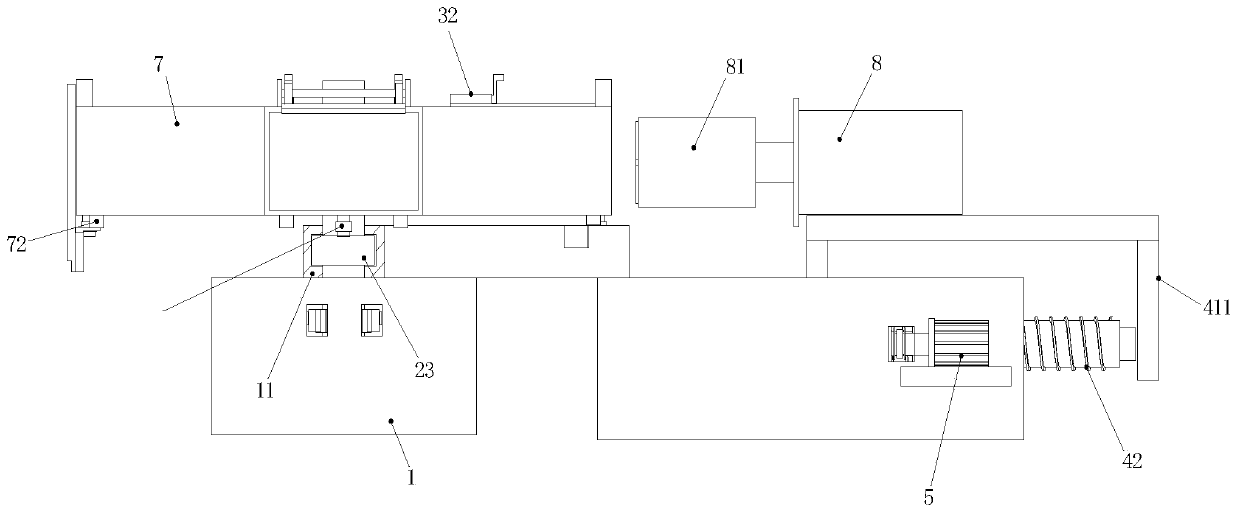
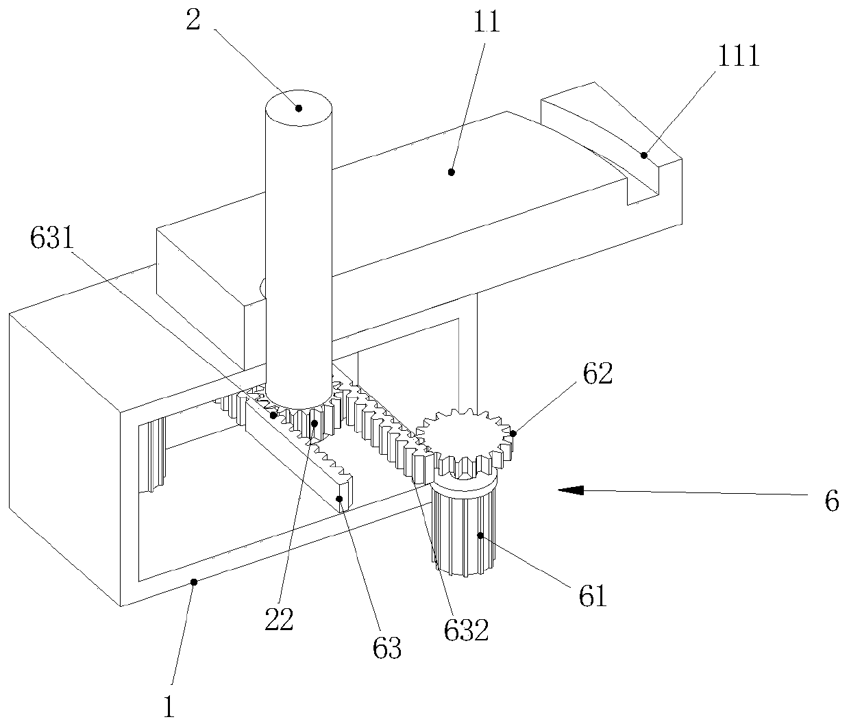
[0026] see Figure 1-5 , the present invention provides a technical solution: a shield machine tool batch experiment mechanism, including a drive frame 1, a drive rod 2 and a drive mechanism 6, the upper surface of the drive frame 1 is welded with a connecting plate 11, and one end of the drive rod 2 The surface of the driving frame 1 and the connecting plate 11 is set through, the upper end of the driving frame 1 is welded with a fixed frame 21, the surface of the...


PUM


Abstract

The invention discloses a shield tunneling machine tool batch experiment mechanism. The mechanism comprises a driving rack, a driving rod and a driving mechanism; a connecting plate is welded on an upper surface of the driving rack, one end of the driving rod is arranged by penetrating the surfaces of the driving rack and the connecting plate; a fixed rack is welded at an upper end of the drivingrack, and simulation racks are equidistantly welded on the surface of the fixed rack; when the soil layers need to be filled in the simulation racks, screens are rotated so that one end of each screenblocks the opening of each simulation rack; one end of a limiting rod is movably inserted into a positioning plate so as to block one end of each simulation rack; the soil layer is input into each simulation rack and the precipitation is performed, so that the tool can perform experiment more accurately; four simulation racks are provided; when one simulation rack performs the experiment, the soil layers are filled in other simulation racks or the soil layers are precipitated; when the experiment of one simulation rack is finished, the other one can directly perform the experiment, and the time waste caused by waiting can be avoided.

Description

technical field [0001] The invention relates to the technical field of shield machines, in particular to a batch experiment mechanism for shield machine tools. Background technique [0002] The shield tunneling method is an important tunnel construction method, which has been widely used in municipal and transportation fields in my country in recent years. The earth pressure balance shield machine is a common equipment for tunnel construction in soft soil. It has become the mainstream of urban underground engineering construction technology. Shield tunneling method construction is a continuous and dynamic process. It has a high degree of automation, saves manpower, and fast construction speed. , One-time hole formation, not affected by climate, ground subsidence can be controlled during excavation, impact on ground buildings can be reduced, and ground traffic will not be affected during underwater excavation. [0003] Before using the shield machine tool in the prior art, a...

Claims


Application Information

Patent Timeline
IPC IPC(8): G01M13/00
CPCG01M13/00
Inventor 夏开民祝勇马玉忠欧长顺
Owner 马鞍山灵山机械设备科技有限公司
Learn More