Fetus suction type obstetric apparatus

A technology of midwifery devices and suction cups, applied in obstetrics and gynecology equipment, etc., can solve the problems of fetal delivery, fetal injury, poor rigidity, etc., and achieve the effect of uniform force

Active Publication Date: 2019-08-02
BEILUN DISTRICT PEOPLES HOSPITAL OF NINGBO CITY
View PDF5 Cites 0 Cited by
  • Summary
  • Abstract
  • Description
  • Claims
  • Application Information

AI Technical Summary

Problems solved by technology

[0003] The purpose of the present invention is to overcome the disadvantages of poor rigidity of the current fetal head suction device, which makes it difficult to deliver the fetus through rotation during delivery; although the forceps are relatively rigid,...

Method used


Image

  • Fetus suction type obstetric apparatus
  • Fetus suction type obstetric apparatus
  • Fetus suction type obstetric apparatus

Examples


Embodiment 1

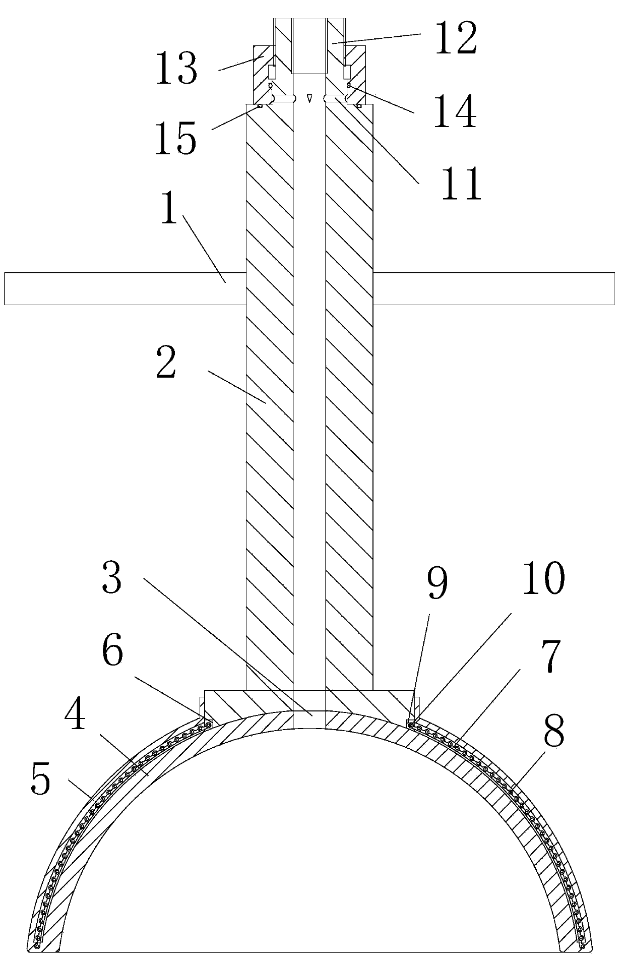
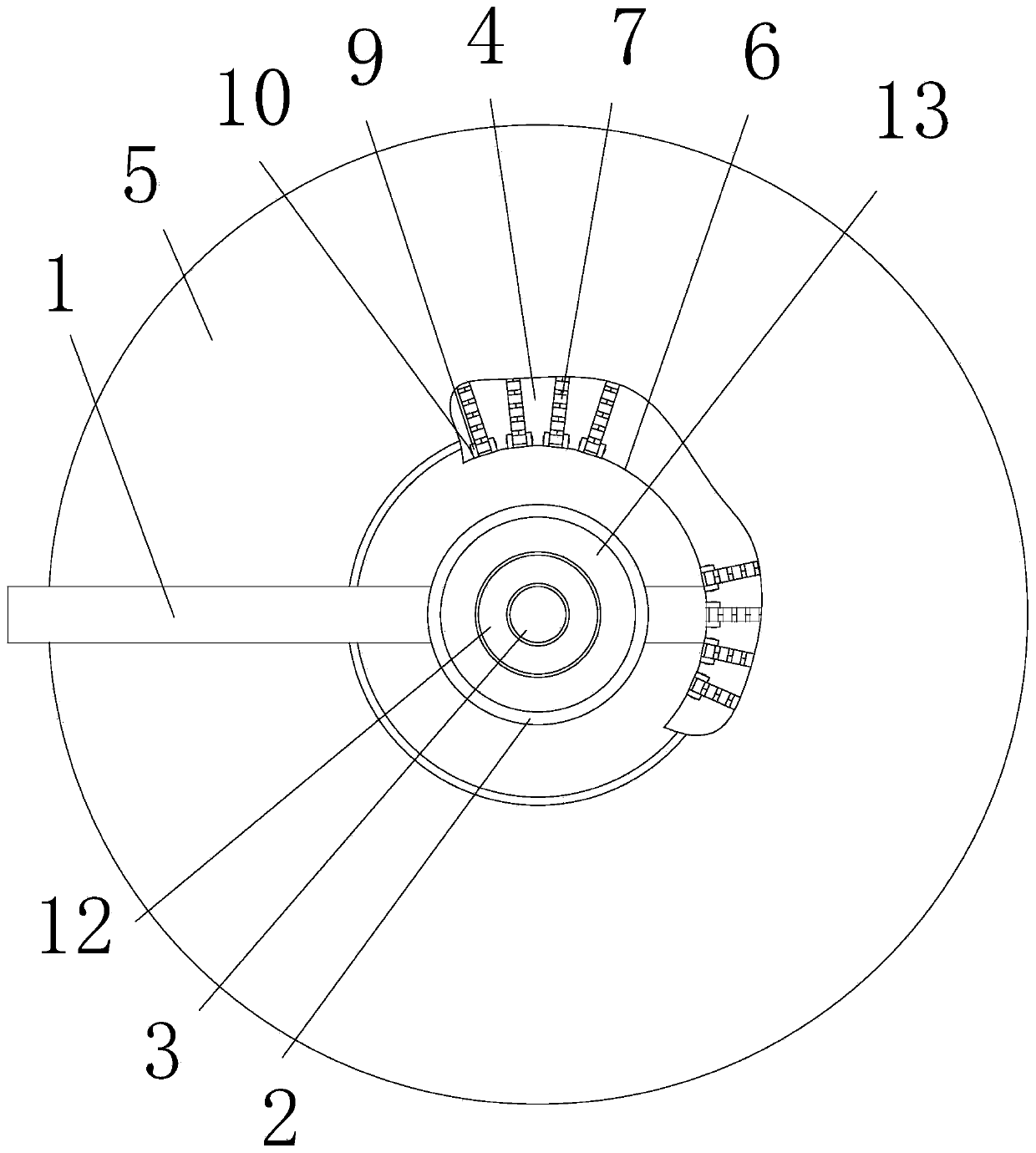
[0019] Embodiment 1, as attached figure 1 , attached figure 2 Shown: a tire-suction type midwifery device, including: a handle tube 2 with two handles 1, a suction cup with a negative pressure suction hole 3 connected to the inner hole of the handle tube 2 and bonded to the lower end of the handle tube 2 4. The rotation auxiliary device arranged on the outside of the suction cup 4, and the negative pressure adjustment device arranged at the upper end of the handle pipe 2.

[0020] The rotation assisting device includes: a protective plate 5 arranged coaxially with the suction cup 4 and whose upper end is bonded to the outside of the handle pipe 2, several chain groups distributed along the circumference between the protective plate 5 and the suction cup 4, located The ring groove 6 surrounding the outer side of the handle pipe 2 and penetrating with the lower end of the handle pipe 2 is provided in the ring groove 6 and has a plurality of connecting ear groups corresponding ...

Embodiment 2

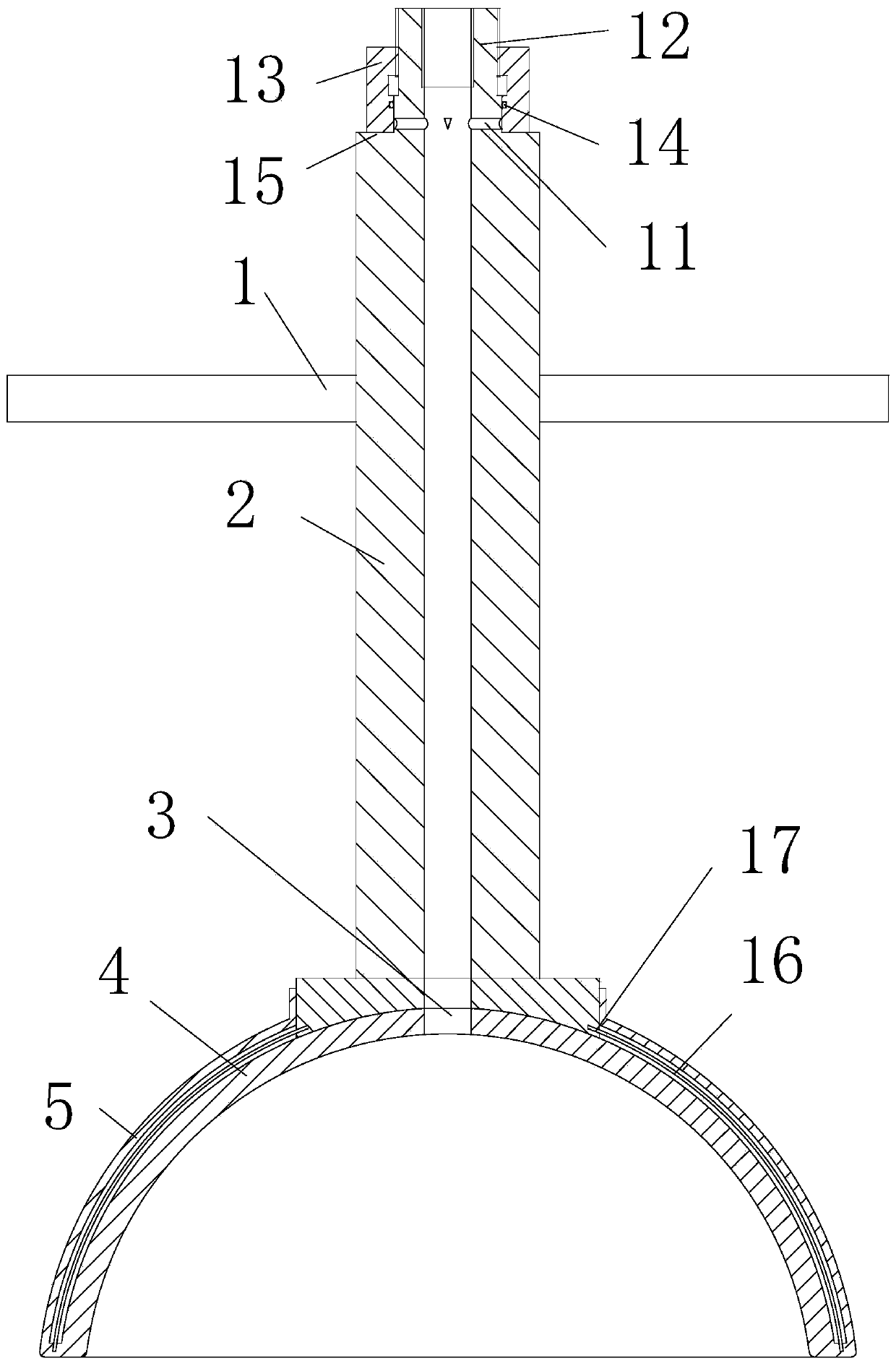
[0024] Embodiment 2, as attached image 3 , attached Figure 4 Shown: a tire-suction type midwifery device, including: a handle tube 2 with two handles 1, a suction cup with a negative pressure suction hole 3 connected to the inner hole of the handle tube 2 and bonded to the lower end of the handle tube 2 4. The rotation auxiliary device arranged on the outside of the suction cup 4, and the negative pressure adjustment device arranged at the upper end of the handle pipe 2.

[0025]The rotation assisting device includes: a protective plate 5 coaxially arranged with the suction cup 4 and connected to the outer circumference of the handle pipe 2 at the upper end, several arc-shaped bar groups located between the protective plate 5 and the suction cup 4 and distributed along the circumference, and A plurality of slot groups corresponding to the lower part of the outer side of the handle tube 2 and corresponding to the arc bar groups; The slots 17 with the same number and one-to-...


PUM

PropertyMeasurementUnit
Thicknessaaaaaaaaaa

Abstract

The invention relates to a fetus suction type obstetric apparatus. The fetus suction type obstetric apparatus comprises a handle pipe, a suction disc, a rotation assisting device and a negative pressure adjusting device, wherein the handle pipe is provided with two handles; a negative pressure suction hole is formed in the suction disc and is communicated with an inner hole of the handle pipe, andthe suction disc is connected with the lower end of the handle pipe; the rotation assisting device is arranged at the outer side of the suction disc; the negative pressure adjusting device is arranged at the upper end of the handle pipe. The fetus suction type obstetric apparatus has the advantages that in the use process, the inner hole of an adjusting pipe is communicated with a negative pressure suction device; in the delivery process, the suction disc is used for sucking the head of a fetus under the function of negative pressure to assist delivery; by rotating the negative pressure adjusting device, the negative pressure can be adjusted, so as to deliver the fetus with minimum suction force; the handles are pulled, the handle pipe drives the suction disc to rotate, the rotation assisting device drives the upper end and lower end of the suction disc to simultaneously rotate, the fetus is smoothly delivered via rotation, and the fetus is not easy to be damaged.

Description

technical field [0001] The invention relates to the technical field of obstetrics, in particular to a tire suction type midwifery device. Background technique [0002] Fetal head aspirator and forceps are commonly used midwifery devices; fetal head aspirator has poor rigidity, and it is difficult to deliver the fetus through rotation during delivery; although forceps are relatively rigid, it is beneficial to deliver the fetus through rotation, but it is easy to The fetus is damaged insufficiently; Therefore, it is an urgent problem to be solved to design a kind of fetal suction type midwifery device that can rotate the fetus during delivery, and the fetus is not easily damaged. Contents of the invention [0003] The purpose of the present invention is to overcome the disadvantages of poor rigidity of the current fetal head suction device, which makes it difficult to deliver the fetus through rotation during delivery; although the forceps are relatively rigid, it is benefic...

Claims


Application Information

Patent Timeline
IPC IPC(8): A61B17/44
CPCA61B17/442
Inventor 孙长冬
Owner BEILUN DISTRICT PEOPLES HOSPITAL OF NINGBO CITY
Why Eureka
Try Eureka