Chip laser engraving equipment and using method thereof

A laser engraving and laser engraving technology, which is applied in laser welding equipment, welding equipment, metal processing equipment, etc., to achieve the effect of high engraving precision

Inactive Publication Date: 2019-08-02
HUBEI HANTAI INTELLIGENT EQUIP
View PDF6 Cites 4 Cited by
  • Summary
  • Abstract
  • Description
  • Claims
  • Application Information

AI Technical Summary

Problems solved by technology

[0003] The object of the present invention is to provide a chip laser marking device and its use method to solve the above problems. The laser printing device and its use method have high engraving and marking precision, and the engraving content is self-defined. Ther

Method used


Image

  • Chip laser engraving equipment and using method thereof
  • Chip laser engraving equipment and using method thereof
  • Chip laser engraving equipment and using method thereof

Examples


Embodiment Construction

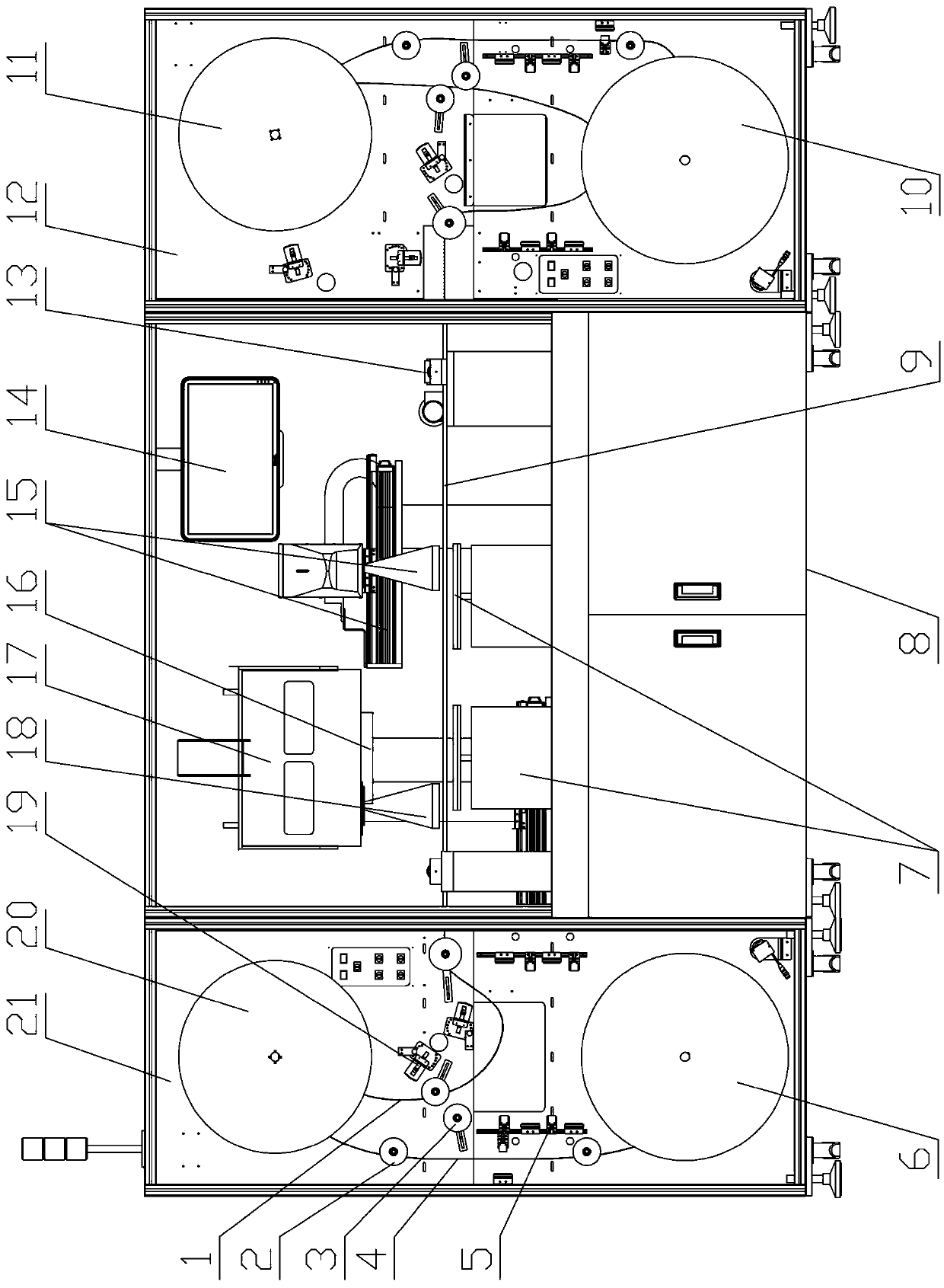
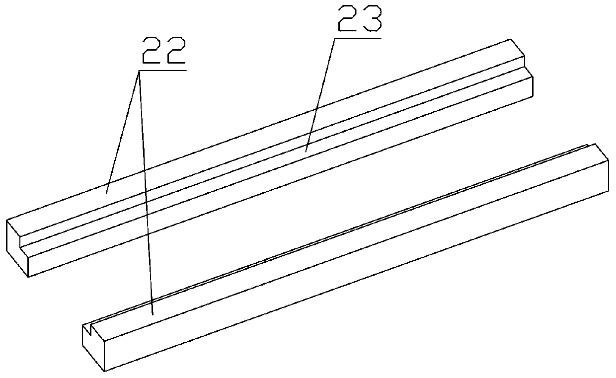
[0024] see Figure 1-Figure 5 , the present invention is a kind of chip laser engraving equipment, comprises feeding room 21, laser engraving room 8 and unloading room 12 successively, is provided with feeding device and static eliminator 19 in the feeding room, is provided with in the unloading room The blanking device and the static eliminator, the left and right ends of the laser engraving room are respectively provided with a chip tape driving device 13, and a chip tape bracket 9 is arranged between the two sets of chip tape driving devices, and the two ends of the chip tape bracket are separated from the two sets of chip tape driving devices. The outer end of the chip tape driving device protrudes; the laser engraving machine 16 and the protective cover 17 are fixedly arranged above the chip tape bracket, and a dust extractor and a dust extraction pipeline are also provided with the inner space of the protective cover, and are connected with the Said laser engraving machi...


PUM


Abstract

The invention relates to chip laser engraving equipment. The equipment sequentially comprises a feeding room, a laser engraving room and a discharging room, wherein a feeding device and an electrostatic eliminating instrument are arranged in the feeding room, a discharging device and an electrostatic eliminating instrument are arranged in the discharging room, chip adhesive tape driving devices are arranged at the left end and the right end of the laser engraving room correspondingly, and a chip adhesive tape supporting frame is arranged between the two chip adhesive tape driving devices; anda laser engraving machine and a protective cover are fixedly arranged above the chip adhesive tape supporting frame, a visual tracking device is further arranged matched with the laser engraving machine, the feeding device, the discharging device, the chip adhesive tape driving devices, the laser engraving machine and the visual tracking device are all controlled by the same master controller, andthe visual tracking device feeds back tracked and located position information of a chip to the master controller. The equipment has the advantages that the engraving precision is high, the engravedcontent can be customized at any time, physical abrasion on the equipment cannot be generated in the whole process, static electricity can be eliminated through the electrostatic eliminating instruments, and no secondary pollution is caused in the whole process.

Description

technical field [0001] The invention relates to the technical field of engraving machining equipment, in particular to a chip laser marking equipment and a method for using the same. Background technique [0002] The position of the chip in the electronic component is like the position of the brain in the human body, and it plays a key role. With the development of modern technology, the size of the chip is getting smaller and smaller, and the performance is getting stronger and stronger. At the same time, the chip itself is becoming more and more fragile, and it is easy to be damaged. Among them, static electricity and physical damage are the most common factors, and they are irreversible. . Therefore, it is necessary to pay attention to anti-static and avoid physical contact when processing it, so a simple control device that can well satisfy the current chip engraving needs to appear urgently. Contents of the invention [0003] The object of the present invention is t...

Claims


Application Information

Patent Timeline
IPC IPC(8): B23K26/362B23K26/70
CPCB23K26/362B23K26/702
Inventor 董清周宗卓余其铭张立汪绪佳
Owner HUBEI HANTAI INTELLIGENT EQUIP
Why Eureka
Try Eureka