
Locomotive for individual rapid transport system, and individual rapid transport system

A technology for rapid transportation and locomotives, applied in the field of rail transit, can solve the problems of reduced locomotive speed, affecting locomotive speed, and short service life, and achieve the effects of preventing large-scale roll, increasing operating speed, and long service life

Pending Publication Date: 2019-08-02
JIANGSU FLYING SHUTTLE INTELLIGENT CO LTD
View PDF7 Cites 5 Cited by
  • Summary
  • Abstract
  • Description
  • Claims
  • Application Information

AI Technical Summary

Problems solved by technology

[0004] In the existing personal rapid transit system, several wheels are usually arranged on both sides of the locomotive. When the locomotive is running on the track, the wheels are just located between the guide rails on both sides of the locomotive. During the operation, when the locomotive deviates from the track or When tilting occurs due to external force (such as lateral wind, etc.), the wheels on the corresponding side are in contact with the track, thereby limiting the deviation or tilting of the locomotive and ensuring the stable operation of the locomotive; however, such a setting usually has some disadvantages, 1. The number of wheels of the locomotive is large, and it is usually necessary to set wheels (at least four) on both sides of the locomotive and at both ends along the length of the locomotive, which is costly; 2. During the actual operation of the locomotive, the locomotive and the locomotive connected For the car, the lateral force in the horizontal direction is usually uneven and changing (such as the influence of the side wind on the locomotive and the car), which will cause the locomotive to be constantly in the track during the forward process of the locomotive. Left deviation, or continuous right deviation (left or right), or left and right deviation alternately, so that the wheels collide with the track continuously, not only easily cause resonance, resulting in particularly loud noise, but also seriously affect the speed of the locomotive, making The speed of the locomotive is greatly reduced. In addition, the wear of the wheels is relatively serious, the service life is short, and frequent replacement is required

Method used


Image

  • Locomotive for individual rapid transport system, and individual rapid transport system
  • Locomotive for individual rapid transport system, and individual rapid transport system
  • Locomotive for individual rapid transport system, and individual rapid transport system

Examples


Embodiment 1

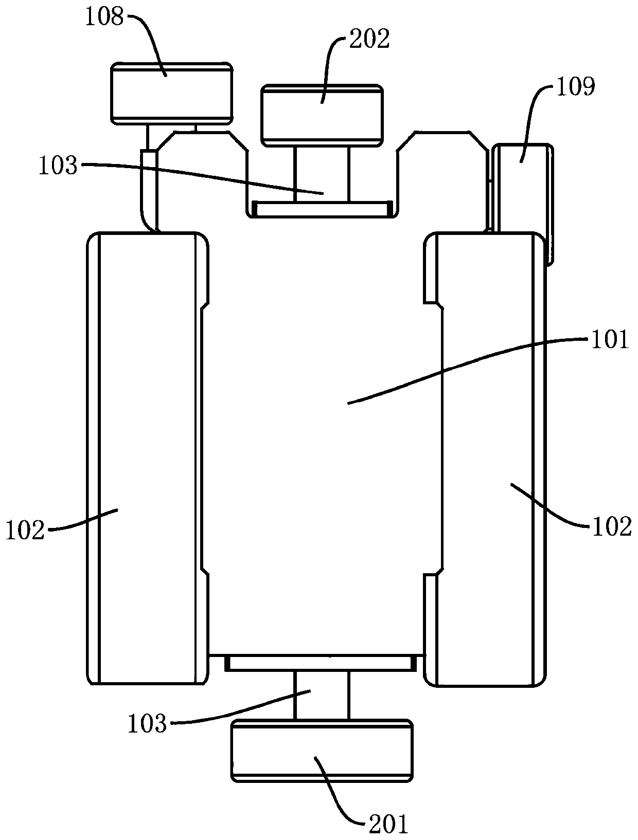
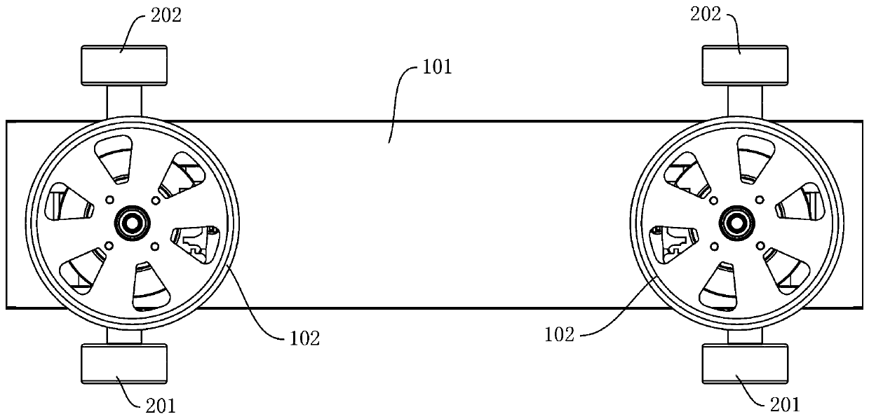
[0034] see figure 1 In this embodiment, a locomotive for a personal rapid transit system is provided, including a locomotive body 101, a first stabilizing wheel 201 for stabilizing the locomotive is provided under the locomotive body 101, and the first stabilizing wheel 201 of the locomotive The rotation axis is perpendicular to the length direction of the locomotive body 101, and the first stabilizing wheel 201 is used to roll (or rotate) along the track of the locomotive so as to balance the force on the locomotive and prevent the locomotive from sideways.

[0035] In this embodiment, by arranging the first stabilizing wheel 201 under the locomotive, it replaces the solution of setting several wheels on both sides of the locomotive in the prior art, which has the following effects:

[0036] 1. The number of first stabilizing wheels 201 required is relatively small, usually only one or two can achieve a good stabilizing effect, thereby effectively saving costs.

[0037] 2. W...

Embodiment 2

[0046] This embodiment provides a personal rapid transit system, including a track and the aforementioned locomotive, the track includes an upper guide rail 301 and a lower guide rail 303, the upper guide rail 301 and the lower guide rail 303 are parallel to each other, and the locomotive is arranged on the upper guide rail 301 and the lower guide rail 303, and is used to run between the upper guide rail 301 and the lower guide rail 303.

[0047] Such as figure 1 As shown, in this embodiment, the side of the locomotive is respectively provided with two road wheels 102, and the two road wheels 102 are in contact with the lower guide rail 303 respectively, and move on the lower guide rail 303, and the upper part of the locomotive is provided with a track changing mechanism, The track changing mechanism includes two track changing swing arms and synchronous connecting rods. One end of the two track changing swing arms is respectively hinged to the synchronous connecting rod, and ...

Embodiment 3

[0053] The main difference between this embodiment 3 and the above-mentioned embodiment 2 is that in the personal rapid transit system provided by this embodiment, the track includes two upper guide rails 301 and two lower guide rails 303, such as Figure 6 As shown, the upper guide rails 301 respectively include rail changing parts 302 arranged along the length direction, the lower rails respectively include stable parts 304 arranged along the length direction, two lower guide rails 303 are arranged in parallel, and the first stabilizing wheels 201 are arranged Between the two stabilizing portions 304, and in contact with at least one stabilizing portion 304 (that is, either in contact with two stabilizing portions 304 at the same time, or only in contact with one of the stabilizing portions 304, and the stabilizing portion 304 is in contact with The track-changing wheel that is guiding the locomotive is on the same side of the locomotive), thereby balancing the force of the l...


PUM


Abstract

The invention relates to a locomotive for an individual rapid transport system, and the individual rapid transport system. The locomotive comprises a locomotive body, a first stabilizing wheel used for stabilizing the locomotive is arranged on the lower part of the locomotive body, the rotary axis of the first stabilizing wheel is perpendicular to the length direction of the locomotive body, and the first stabilizing wheel is used for rolling along with a rail of the locomotive. The individual rapid transport system is simple and compact in structure and low in cost, stable operation is facilitated, resonance is prevented, noise is reduced, the problem of eccentricity of the locomotive during monorail operation can be effectively solved, and force balance of the locomotive is facilitated.

Description

technical field [0001] The invention relates to the technical field of rail transit, in particular to a locomotive used in a personal rapid transit system and the personal rapid transit system. Background technique [0002] The personal rapid transit system is a new type of rail transit system that can provide uninterrupted transportation services on demand, and has developed rapidly in recent years. [0003] Existing personal rapid transit systems usually include a locomotive (or called a vehicle) and a track. The locomotive is relatively small, and a car is suspended below the locomotive. The car is used to accommodate passengers. The track usually adopts a suspended track; the locomotive is usually arranged on In the track, in the actual operation process, the locomotive realizes forward movement and track change through the cooperation of the track and the track, thereby driving the passengers in the car to reach different stations. [0004] In the existing personal rap...

Claims


Application Information

Patent Timeline
Patent Type & Authority Applications(China)
IPC IPC(8): B61B12/00B61B12/02
CPCB61B12/02B61B12/00
Inventor 何先志刘江胡震
Owner JIANGSU FLYING SHUTTLE INTELLIGENT CO LTD
Learn More